


About Gears
More
High-Power Metal Gears
and Crossed Left-Hand
Gear (Sold Separately)
Right-Hand Teeth
(Sold Separately)

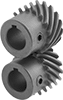
The helical teeth on these gears stay in contact for longer than straight teeth, which allows them to transmit higher loads at higher speeds than spur gears.
For gears to mesh correctly, they must have the same pressure angle and pitch. All of these gears transmit motion in a straight line—make sure to get one left-hand and one right-hand gear. To change speed and torque in your assembly, pair two gears with different numbers of teeth.
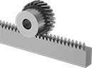
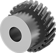
Parallel helical components have a 21 1/2° helix angle so they only transmit motion in a straight line since the helix angle is so small. Made from alloy steel, these gears resist abrasion and are stronger than carbon steel gears. Their teeth are ground, so they're more precise than gears with rolled teeth. Pair them with a rack or a gear that has a different tooth direction.
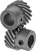
Crossed helical gears, also known as screw gears, can be configured to transmit motion at a 90° angle. To transmit motion at a 90° angle, pair two gears with the same tooth direction. To avoid wearing down gears, which happens when you use the same material, we recommend mating gears with different materials. Made from carbon steel, these gears are strong, but not as strong as alloy steel gears.
Gears with hardened teeth have better wear resistance than gears with teeth that are not hardened.
![]() For technical drawings and 3-D models, click on a part number.
For technical drawings and 3-D models, click on a part number.
Hub | Keyway | ||||||||||||||
|---|---|---|---|---|---|---|---|---|---|---|---|---|---|---|---|
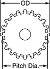
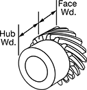
| Gear Pitch | Number of Teeth | Helix Angle | Gear Pitch Dia. | OD | Face Wd. | Overall Wd. | For Shaft Dia. | Teeth Heat Treatment | Dia. | Wd. | Wd. | Dp. | Set Screw Thread Size | Each | |
Left Hand | |||||||||||||||
Keyed Bore with Set Screw—1137 Carbon Steel | |||||||||||||||
| 16 | 16 | 45° | 1" | 1.09" | 1/2" | 1" | 1/2" | Hardened | 0.86" | 0.5" | 0.125" | 0.062" | 1/4"-20 | 0000000 | 000000 |
| 16 | 24 | 45° | 1 1/2" | 1.59" | 1/2" | 1" | 5/8" | Hardened | 1.37" | 0.5" | 0.187" | 0.094" | 1/4"-20 | 0000000 | 000000 |
| 16 | 32 | 45° | 2" | 2.09" | 1/2" | 1" | 5/8" | Hardened | 1.87" | 0.5" | 0.187" | 0.094" | 1/4"-20 | 0000000 | 000000 |
| 16 | 48 | 45° | 3" | 3.09" | 1/2" | 1" | 5/8" | Hardened | 2.5" | 0.5" | 0.187" | 0.094" | 1/4"-20 | 0000000 | 000000 |
| 12 | 18 | 45° | 1 1/2" | 1.62" | 3/4" | 1.25" | 5/8" | Hardened | 1.34" | 0.5" | 0.187" | 0.094" | 1/4"-20 | 0000000 | 000000 |
Right Hand | |||||||||||||||
Keyed Bore with Set Screw—1137 Carbon Steel | |||||||||||||||
| 16 | 16 | 45° | 1" | 1.09" | 1/2" | 1" | 1/2" | Hardened | 0.86" | 0.5" | 0.125" | 0.062" | 1/4"-20 | 0000000 | 00000 |
| 16 | 24 | 45° | 1 1/2" | 1.59" | 1/2" | 1" | 5/8" | Hardened | 1.37" | 0.5" | 0.187" | 0.094" | 1/4"-20 | 0000000 | 000000 |
| 16 | 32 | 45° | 2" | 2.09" | 1/2" | 1" | 5/8" | Hardened | 1.87" | 0.5" | 0.187" | 0.094" | 1/4"-20 | 0000000 | 000000 |
| 16 | 48 | 45° | 3" | 3.09" | 1/2" | 1" | 5/8" | Hardened | 2.5" | 0.5" | 0.187" | 0.094" | 1/4"-20 | 0000000 | 000000 |
| 12 | 18 | 45° | 1 1/2" | 1.62" | 3/4" | 1.25" | 5/8" | Hardened | 1.34" | 0.5" | 0.187" | 0.094" | 1/4"-20 | 0000000 | 000000 |
Hub | ||||||||||||
|---|---|---|---|---|---|---|---|---|---|---|---|---|
| Module | Number of Teeth | Helix Angle | Gear Pitch Dia., mm | OD, mm | Face Wd., mm | Overall Wd., mm | For Shaft Dia., mm | Teeth Heat Treatment | Dia., mm | Wd., mm | Each | |
Left Hand | ||||||||||||
Round Bore—4140 Alloy Steel | ||||||||||||
| 1 | 20 | 21 1/2° | 20 | 22 | 8 | 18 | 6 | Hardened | 17 | 10 | 00000000 | 000000 |
| 1 | 30 | 21 1/2° | 30 | 32 | 8 | 18 | 10 | Hardened | 25 | 10 | 00000000 | 000000 |
| 1 | 44 | 21 1/2° | 44 | 46 | 8 | 18 | 10 | Hardened | 30 | 10 | 00000000 | 000000 |
Right Hand | ||||||||||||
Round Bore—4140 Alloy Steel | ||||||||||||
| 1 | 20 | 21 1/2° | 20 | 22 | 8 | 18 | 6 | Hardened | 17 | 10 | 00000000 | 00000 |
| 1 | 30 | 21 1/2° | 30 | 32 | 8 | 18 | 10 | Hardened | 25 | 10 | 00000000 | 000000 |
| 1 | 44 | 21 1/2° | 44 | 46 | 8 | 18 | 10 | Hardened | 30 | 10 | 00000000 | 000000 |


Hub | ||||||||||||
|---|---|---|---|---|---|---|---|---|---|---|---|---|
| Module | Number of Teeth | Helix Angle | Gear Pitch Dia., mm | OD, mm | Face Wd., mm | Overall Wd., mm | For Shaft Dia., mm | Teeth Heat Treatment | Dia., mm | Wd., mm | Each | |
Left Hand | ||||||||||||
Round Bore—Black-Oxide 1045 Carbon Steel | ||||||||||||
| 1 | 13 | 45° | 18 | 20.38 | 10 | 20 | 6 | Not Hardened | 15 | 10 | 00000000 | 000000 |
| 1 | 26 | 45° | 36 | 38.77 | 10 | 20 | 10 | Not Hardened | 30 | 10 | 00000000 | 00000 |
| 1 | 30 | 45° | 42 | 44.43 | 10 | 20 | 10 | Not Hardened | 35 | 10 | 00000000 | 00000 |
| 1.5 | 10 | 45° | 21 | 24.21 | 15 | 25 | 8 | Not Hardened | 16 | 10 | 00000000 | 00000 |
| 1.5 | 13 | 45° | 27 | 30.58 | 15 | 25 | 10 | Not Hardened | 23 | 10 | 00000000 | 00000 |
| 1.5 | 26 | 45° | 55 | 58.15 | 15 | 25 | 12 | Not Hardened | 40 | 10 | 00000000 | 00000 |
Right Hand | ||||||||||||
Round Bore—Black-Oxide 1045 Carbon Steel | ||||||||||||
| 1 | 13 | 45° | 18 | 20.38 | 10 | 20 | 6 | Not Hardened | 15 | 10 | 00000000 | 00000 |
| 1 | 26 | 45° | 36 | 38.77 | 10 | 20 | 10 | Not Hardened | 30 | 10 | 00000000 | 00000 |
| 1 | 30 | 45° | 42 | 44.43 | 10 | 20 | 10 | Not Hardened | 35 | 10 | 00000000 | 00000 |
| 1.5 | 10 | 45° | 21 | 24.21 | 15 | 25 | 8 | Not Hardened | 16 | 10 | 00000000 | 00000 |
| 1.5 | 13 | 45° | 27 | 30.58 | 15 | 25 | 10 | Not Hardened | 23 | 10 | 00000000 | 00000 |
| 1.5 | 26 | 45° | 55 | 58.15 | 15 | 25 | 12 | Not Hardened | 40 | 10 | 00000000 | 00000 |
High-Power Metal Miter Gears


Also known as spiral miter gears, these gears have curved teeth that stay in contact longer than straight teeth so they handle heavier loads at higher speeds. They run quieter than standard miter gears because the teeth gradually engage. Use them to transmit motion at a right angle while maintaining shaft speed and torque. Gears are carbon steel for strength. Teeth are hardened for wear resistance.
Gears must be identical in order to mesh correctly; they're sold as a pair.
![]() For technical drawings and 3-D models, click on a part number.
For technical drawings and 3-D models, click on a part number.
Hub | Keyway | |||||||||||||||
|---|---|---|---|---|---|---|---|---|---|---|---|---|---|---|---|---|
| Gear Pitch | Number of Teeth | Pressure Angle | Gear Pitch Dia. | OD | Face Wd. | Overall Wd. | For Shaft Dia. | Mounting Distance | Material | Dia. | Wd. | Wd. | Dp. | Set Screw Thread Size | Pair | |
Keyed Bore with Set Screw | ||||||||||||||||
| 18 | 18 | 20° | 1" | 1.07" | 0.22" | 0.74" | 3/8" | 1.062" | 1117 Carbon Steel | 0.75" | 0.44" | 0.094" | 0.047" | 10-32 | 000000 | 0000000 |
| 12 | 15 | 20° | 1 1/4" | 1.36" | 0.3" | 0.86" | 1/2" | 1.25" | 1117 Carbon Steel | 1" | 0.5" | 0.125" | 0.063" | 1/4"-20 | 000000 | 000000 |
| 12 | 18 | 20° | 1 1/2" | 1.61" | 0.34" | 1.02" | 5/8" | 1.5" | 1117 Carbon Steel | 1.25" | 0.56" | 0.188" | 0.094" | 5/16"-18 | 000000 | 000000 |
| 10 | 20 | 20° | 2" | 2.13" | 0.47" | 1.36" | 3/4" | 2" | 1117 Carbon Steel | 1.625" | 0.78" | 0.188" | 0.094" | 5/16"-18 | 000000 | 000000 |
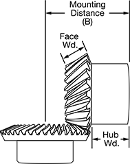
High-Power Metal Bevel Gears
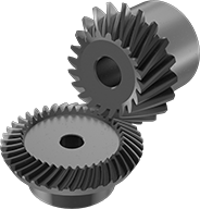
Made from carbon steel with spiral teeth, these gears handle heavier loads at higher speeds than bevel gears with straight teeth because their teeth stay in contact longer. Their teeth engage gradually, which reduces vibration and noise, and they’re hardened for extra wear resistance. Use these gears to transmit motion at a right angle while changing shaft speed and torque. They reduce speeds at ratios of 2:1, 3:1, or 4:1. Customize their machinable bore to fit them on a variety of shafts. They’re also known as spiral bevel gears.
A complete set consists of a gear and pinion (sold separately). The gear is larger than the pinion, but for them to mesh correctly, they must have the same pressure angle, module, and face width.
Speed ratio is the ratio by which shaft speed is reduced when transferring motion from pinion to gear. To increase shaft speed, transfer motion from gear to pinion. Changing shaft speed also changes torque: as speed decreases, torque increases.
![]() For technical drawings and 3-D models, click on a part number.
For technical drawings and 3-D models, click on a part number.
Hub | |||||||||||||
|---|---|---|---|---|---|---|---|---|---|---|---|---|---|
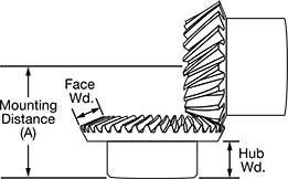
| Face Width, mm | Pressure Angle | Speed Ratio | Number of Teeth | Gear Pitch Dia., mm | OD, mm | Overall Width, mm | For Shaft Diameter, mm | Mounting Distance (A), mm | Material | Diameter, mm | Width, mm | Each | |
Machinable Round Bore | |||||||||||||
| 6 | 20° | 2:1 | 40 | 40 | 40.52 | 15 | 8-18 | 22 | Black-Oxide 1045 Carbon Steel | 25 | 8 | 0000000 | 000000 |
| 10 | 20° | 2:1 | 40 | 60 | 60.75 | 24.9 | 10-25 | 35 | Black-Oxide 1045 Carbon Steel | 38 | 15 | 0000000 | 00000 |
| 12 | 20° | 4:1 | 60 | 90 | 90.36 | 24.1 | 12-45 | 32 | Black-Oxide 1045 Carbon Steel | 60 | 12 | 0000000 | 000000 |
| 15 | 20° | 3:1 | 45 | 90 | 90.67 | 30.3 | 12-30 | 40 | Black-Oxide 1045 Carbon Steel | 40 | 17 | 0000000 | 000000 |
Hub | |||||||||||||
|---|---|---|---|---|---|---|---|---|---|---|---|---|---|
| Face Width, mm | Pressure Angle | Speed Ratio | Number of Teeth | Gear Pitch Dia., mm | OD, mm | Overall Width, mm | For Shaft Diameter, mm | Mounting Distance (B), mm | Material | Diameter, mm | Width, mm | Each | |
Machinable Round Bore | |||||||||||||
| 6 | 20° | 2:1 | 20 | 20 | 22.08 | 13.7 | 6-9 | 28 | Black-Oxide 1045 Carbon Steel | 16 | 7 | 0000000 | 000000 |
| 10 | 20° | 2:1 | 20 | 30 | 33.08 | 25.5 | 8-15 | 46 | Black-Oxide 1045 Carbon Steel | 25 | 15 | 0000000 | 00000 |
| 12 | 20° | 4:1 | 15 | 23 | 26.09 | 23 | 8-10 | 56 | Black-Oxide 1045 Carbon Steel | 18 | 10 | 0000000 | 00000 |
| 15 | 20° | 3:1 | 15 | 30 | 34.78 | 29.7 | 10-14 | 60 | Black-Oxide 1045 Carbon Steel | 24 | 14 | 0000000 | 00000 |