


Choosing an Electrical Switch
More
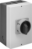
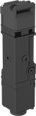
Enclosed Disconnect Switches
Cut power and keep it isolated to prevent equipment from starting up during inspection and maintenance. These switches are housed in a protective enclosure that resists denting, chipping, and cracking. Mount them to the wall when you run out of space in an electrical panel.
Switches with lockout secure in the off position with a padlock with a maximum shackle diameter of 5/16” (not included).
Photovoltaic switches can be used with photovoltaic cells which convert sunlight into electricity.
![]() For technical drawings and 3-D models, click on a part number.
For technical drawings and 3-D models, click on a part number.
Switching | Plastic Housing with Red Actuator | ||||||
|---|---|---|---|---|---|---|---|
| Current, A | Voltage | Industry Designation | Ht. | Wd. | Environmental Rating | Each | |
Stays Switched (Maintained) | |||||||
2 Circuits with Lockout/Photovoltaic | |||||||
| 32 | 800V DC | DPST | 11" | 7 1/2" | IP66, IP67, NEMA 3S, NEMA 6P, NEMA 12 | 0000000 | 0000000 |
| "Main Switch" Label with Adhesive Back—13/16" Ht. × 3 3/16" Wd. | 0000000 | Each | 000000 |
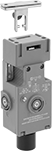
Frame-Mounted Safety Switches
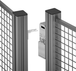
Also known as interlock switches, these ensure the safety of personnel by automatically shutting off power to machinery when an access door opens. Mount the switch to the door frame and mount a key to the door so that the key is inserted into the switch when the door is closed. When the door opens, the key is removed from the switch and the machine shuts down. They’re often used with machine guards for large robots.
All switches require an actuator key, but not all include one—check whether you need to pick out a separate actuator key. For some switch styles, you can also select the mounting orientation of the key. Flexible keys pivot at least 15°, making them easier to align with switches during installation.
Style A-G switches have positive-force, normally closed contacts that will open a circuit when the switch is actuated even if a spring fails or the contacts stick.
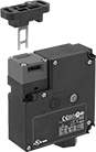
Style J switches have extra safety controls to prevent you from getting trapped next to running machinery. They actuate with the turn of a portable key. Bring the key when you enter an enclosure to ensure machinery won’t start while you’re inside, even if the door closes behind you. As an added fail-safe, a rear release button lets you cut power from inside of enclosures if needed. These switches have light-up indicators that show when they're properly installed and whether they're actuated.
IP67 rated switches protect against temporary submersion. NEMA 6 rated switches protect against both temporary submersion and washdowns.
![]() For technical drawings and 3-D models, click on a part number.
For technical drawings and 3-D models, click on a part number.


Housing | Conduit | ||||||||||||||||
|---|---|---|---|---|---|---|---|---|---|---|---|---|---|---|---|---|---|
| Style | No. of Circuits Controlled | Switch Starting Position | Switch Action | No. of Terminals | Industry Designation | Switching Current @ Voltage | Max. Voltage | Ht. | Wd. | Dp. | Trade Size | Thread Size | Thread Type | Key Included | Environmental Rating | Each | |
Wire Lead Connection with Positive-Force Normally Closed Contacts | |||||||||||||||||
| A | 2 | 1 Off (Normally Open) and 1 On (Normally Closed) | Stays Switched (Maintained) | 2 | DPST-1NO/1NC | 8 A @ 120 V AC, 4 A @ 24 V DC | 250V AC 24V DC | 3.3" | 1.2" | 1.2" | __ | M16 | Metric | Yes | IP67 | 00000000 | 0000000 |
Screw Terminal Connection with Positive-Force Normally Closed Contacts | |||||||||||||||||
| B | 2 | 1 Off (Normally Open) and 1 On (Normally Closed) | Stays Switched (Maintained) | 4 | DPST-1NO/1NC | 5 A @ 120 V AC, 2 A @ 24 V DC | 500V AC 250V DC | 3" | 1" | 1.1" | 1/2 | __ | NPT | Yes | IP67, NEMA 6 | 00000000 | 000000 |
| C | 3 | 1 Off (Normally Open) and 2 On (Normally Closed) | Stays Switched (Maintained) | 3 | 3PST-1NO/2NC | 8 A @ 120 V AC, 4 A @ 24 V DC | 600V AC 250V DC | 3.5" | 2.1" | 1.2" | 1/2 | __ | NPT | Yes | IP67 | 00000000 | 000000 |
| C | 3 | 1 Off (Normally Open) and 2 On (Normally Closed) | Stays Switched (Maintained) | 6 | 3PST-1NO/2NC | 4 A @ 230 V AC, 4 A @ 24 V DC | 500V AC 24V DC | 3.5" | 2" | 1.2" | __ | M16 | Metric | Yes | IP67 | 00000000 | 000000 |
| D | 3 | 1 Off (Normally Open) and 2 On (Normally Closed) | Stays Switched (Maintained) | 6 | 3PST-1NO/2NC | 6 A @ 120 V AC, 0.27 A @ 24 V DC | 240V AC 250V DC | 3.8" | 1.2" | 1.2" | 1/2 | __ | NPT | Yes | IP67 | 00000000 | 00000 |
| E | 2 | 1 Off (Normally Open) and 1 On (Normally Closed) | Stays Switched (Maintained) | 4 | DPST-1NO/1NC | 8 A @ 230 V AC, 5 A @ 24 V DC | 400V AC 24V DC | 4.2" | 2" | 1.6" | __ | M20 | Metric | No | IP67 | 00000000 | 00000 |
| E | 2 | 2 On (Normally Closed) | Stays Switched (Maintained) | 4 | DPST-NC | 8 A @ 230 V AC, 5 A @ 24 V DC | 400V AC 24V DC | 4.2" | 2" | 1.6" | __ | M20 | Metric | No | IP67 | 00000000 | 00000 |
| F | 2 | 1 Off (Normally Open) and 1 On (Normally Closed) | Stays Switched (Maintained) | 4 | DPST-1NO/1NC | 2 A @ 400 V AC | 400V AC | 4.4" | 1.6" | 1.6" | __ | M20 | Metric | No | IP67 | 000000000 | 00000 |
| F | 2 | 1 Off (Normally Open) and 1 On (Normally Closed) | Stays Switched (Maintained) | 4 | DPST-1NO/1NC | 2 A @ 400 V AC | 400V AC | 4.4" | 1.6" | 1.6" | 1/2 | __ | BSPP | No | IP67 | 000000000 | 000000 |
| F | 2 | 1 Off (Normally Open) and 1 On (Normally Closed) | Stays Switched (Maintained) | 4 | DPST-1NO/1NC | 2 A @ 400 V AC | 400V AC | 4.4" | 1.6" | 1.6" | 1/2 | __ | NPT | No | IP67 | 000000000 | 000000 |
| F | 2 | 2 On (Normally Closed) | Stays Switched (Maintained) | 4 | DPST-NC | 2 A @ 400 V AC | 400V AC | 4.4" | 1.6" | 1.6" | __ | M20 | Metric | No | IP67 | 000000000 | 00000 |
| F | 2 | 2 On (Normally Closed) | Stays Switched (Maintained) | 4 | DPST-NC | 2 A @ 400 V AC | 400V AC | 4.4" | 1.6" | 1.6" | 1/2 | __ | BSPP | No | IP67 | 000000000 | 00000 |
| F | 2 | 2 On (Normally Closed) | Stays Switched (Maintained) | 4 | DPST-NC | 2 A @ 400 V AC | 400V AC | 4.4" | 1.6" | 1.6" | 1/2 | __ | NPT | No | IP67 | 000000000 | 000000 |
Screw Terminal Connection with Positive-Force Normally Closed Contacts and Rotating Head | |||||||||||||||||
| D | 3 | 1 Off (Normally Open) and 2 On (Normally Closed) | Stays Switched (Maintained) | 6 | 3PST-1NO/2NC | 10 A @ 120 V AC, 2.5 A @ 125 V DC | 240V AC 250V DC | 3.8" | 1.2" | 1.2" | __ | M20 | Metric | No | IP67 | 00000000 | 00000 |
| G | 3 | 1 Off (Normally Open) and 2 On (Normally Closed) | Stays Switched (Maintained) | 6 | 3PST-1NO/2NC | 10 A @ 230 V AC, 4 A @ 24 V DC | 250V AC 24V DC | 4.3" | 1.6" | 1.4" | __ | M20 | Metric | No | IP67 | 00000000 | 000000 |
Screw Terminal Connection with Rotating Head | |||||||||||||||||
| H | 4 | 2 Off (Normally Open) and 2 On (Normally Closed) | Stays Switched (Maintained) | 8 | 4PST-2NO/2NC | 2.5 A @ 120 V AC, 1 A @ 125 V DC | 120V AC 125V DC | 7.1" | 1.5" | 1.5" | 1/2 | __ | NPT | No | IP67 | 00000000 | 000000 |
Screw Terminal Connection with Rear Release Button, Portable Key, and LED Status Indicator | |||||||||||||||||
| J | 6 | 2 Off (Normally Open) and 4 On (Normally Closed) | Stays Switched (Maintained) | 12 | 6PST-2NO/4NC | 3 A @ 240 V AC, 2.5 A @ 250 V DC | 240V AC 250V DC | 5.2" | 4.6" | 2.2" | __ | M20 | Metric | Yes | IP67 | 000000000 | 000000 |


O'all | |||||||
|---|---|---|---|---|---|---|---|
| Angle Range | Adjustability | Lg. | Wd. | Mounting Fasteners Included | Each | ||
Straight Keys | |||||||
| For Style E | __ | __ | 80 mm | 32 mm | No | 00000000 | 000000 |
| For Style F | __ | __ | 53.7 mm | 52.4 mm | No | 000000000 | 00000 |
| For Style G | __ | __ | 86 mm | 32 mm | No | 00000000 | 00000 |
| For Style H | __ | __ | 48.5 mm | 35 mm | No | 00000000 | 00000 |
| For Style J | __ | __ | 61.5 mm | 40 mm | No | 000000000 | 00000 |
90° Angle Keys | |||||||
| For Style E | __ | __ | 65.5 mm | 32 mm | No | 00000000 | 00000 |
| For Style J | __ | __ | 45 mm | 40 mm | No | 000000000 | 00000 |
Flexible Keys | |||||||
| For Style D | 0°-15° | Up/Down/Left/Right | 48.9 mm | 55 mm | No | 000000000 | 00000 |
| For Style F | 0°-18° | Left/Right | 80.7 mm | 40 mm | No | 000000000 | 00000 |
| For Style G | 0°-15° | Up/Down/Left/Right | 105 mm | 40 mm | No | 00000000 | 000000 |
| For Style H | 0°-15° | Up/Down/Left/Right | 50.4 mm | 55 mm | No | 00000000 | 00000 |
| For Style J | 0°-18° | Left/Right | 70 mm | 40 mm | No | 000000000 | 00000 |
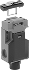
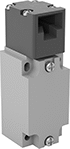
Access-Delay Frame-Mounted Safety Switches
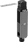
Delay access to hazardous areas until conditions are safe; use these switches with machines that take time to stop after they are turned off. Mount the switch to the door frame and mount the key to the door so that the key is inserted into the switch when the door is closed. When the door is pulled, the key is held in place with 225 lbs. of force until the switch receives a signal from a time-delay relay, motion sensor, or position sensor (not included) that the machine’s motion has stopped. After the motion has stopped, the key can be removed from the switch, releasing the access door. They’re often used with machine guards. All have positive-force, normally-closed contacts that will open a circuit when the switch is actuated even if a spring fails or the contacts stick. They’re rated for protection from washdowns and temporary submersion.
Style A and B have a key entry on the top and side of the switch.
Style C has a key entry on two opposite sides of the switch.
Emergency override keys (sold separately) bypass the access delay feature.
![]() For technical drawings and 3-D models, click on a part number.
For technical drawings and 3-D models, click on a part number.
Housing | ||||||||||||||||
|---|---|---|---|---|---|---|---|---|---|---|---|---|---|---|---|---|
| Style | No. of Circuits Controlled | Switch Starting Position | Switch Action | No. of Terminals | Industry Designation | Switching Current @ Voltage | Max. Voltage | Input Voltage | Holding Force, lbs. | Ht. | Wd. | Dp. | Wire Connection Type | Conduit Trade Size | Each | |
Positive-Force Normally Closed Contacts | ||||||||||||||||
| A | 3 | 1 Off (Normally Open) and 2 On (Normally Closed) | Stays Switched (Maintained) | 6 | 3PST-1NO/2NC | 5 A @ 120 V AC, 2 A @ 24 V DC | 500V AC 250V DC | 24V AC, 24V DC | 225 | 4.7" | 2.3" | 1.4" | Screw Terminals | 1/2 | 0000000 | 0000000 |
| A | 3 | 1 Off (Normally Open) and 2 On (Normally Closed) | Stays Switched (Maintained) | 6 | 3PST-1NO/2NC | 5 A @ 120 V AC, 2 A @ 24 V DC | 500V AC 250V DC | 110V AC | 225 | 4.7" | 2.3" | 1.4" | Screw Terminals | 1/2 | 0000000 | 000000 |
| B | 3 | 1 Off (Normally Open) and 2 On (Normally Closed) | Stays Switched (Maintained) | 14 | 3PST-1NO/2NC | 3 A @ 120 V AC, 2.5 A @ 24 V DC | 250V DC 240V AC | 24V DC | 225 | 3.7" | 3.5" | 1.4" | Screw Terminals | 1/2 | 0000000 | 000000 |
Positive-Force Normally Closed Contacts and Rotating Head | ||||||||||||||||
| C | 4 | 2 Off (Normally Open) and 2 On (Normally Closed) | Stays Switched (Maintained) | 8 | 4PST-2NO/2NC | 4 A @ 120 V AC, 4 A @ 24 V DC | 240V AC 24V DC | 24V AC, 24V DC | 225 | 7.6" | 1.2" | 1.6" | Screw Terminals | 1/2 | 0000000 | 000000 |
| Emergency Override Key for Style A | 0000000 | Each | 000000 |