


About Timer Relays
More
Dual-Channel DIN-Rail Mount Multifunction Timer Relays
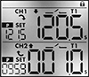

Control two steps of an electrical process from a single relay—with two fully independent channels and 30 different functions, these relays give you a wide range of possibilities. Each channel has its own output, so you can run two different functions (one per circuit) at the same time. Mount them to 35 mm DIN rails (also known as DIN 3 rail) and connect them to lighting systems, conveyors, electric motors, and other systems. These relays are UL Listed, C-UL Listed, and CE Marked, meaning they meet U.S. and international safety standards.
View times, function names, and on/off status for both channels at once using the digital display. You can program these relays with a joystick on the face, which is easier to use than the rotary dials on traditional relays. You can also program them using an Android phone with NFC (near field communication) capability, which is commonly used for mobile payment. Once you select the functions you need, hold the phone against the relay to program.
Connect switches to inputs on these relays to trigger, pause, and reset functions. Turning on a switch connected to the pause input stops functions until the switch is turned off. A switch connected to the reset input will start functions from the beginning. If the relay is actively receiving a signal, the function will restart right away. If there is no signal, the function will stop and reset, so it starts from the beginning the next time it’s triggered. You can use switches to pause or reset both channels at once, or for one channel only.
Use relays with proximity sensor compatibility to activate functions when your sensor is triggered, such as when an object approaches or a liquid level changes. These relays are compatible with both standard styles of sensors, PNP and NPN, and are often used for warning signals, motion-detecting light and heating systems, and automated assembly lines.
Although these relays have 30 different functions, they all fall into 10 categories. Within these categories, you can select different functions to allow you to add a switch, program a delay, or change how the relay responds to a trigger (turning on or off, pausing, or resetting).
Manual Switch Control—Use these functions to turn the relay on and off with a switch.
Fixed On/Off—The on function keeps the relay on whenever input voltage is applied; it will only turn off if the voltage is removed. The off function keeps the relay in an off state, even if input voltage is applied.
Switch-On (Single-Shot)—These functions require a switch to activate the relay, which stays on for the programmed amount of time. For example, lights in a storage room are turned on with a switch and stay on for a set time before turning off.
Delayed Start (Delay-on-Make)—These functions allow you to set how long it takes for the relay to turn on after input voltage is applied. For example, a drill starts pumping lubricant immediately, but it does not start rotating until the set time has elapsed.
Delayed Switch-Off (Delay-on-Break)—These functions use a switch instead of input voltage. When the switch is turned off, the relay remains on for a programmed amount of time before turning off. For example, a projector’s light is turned off with a switch, but its cooling fan continues to run for a set time.
Delayed Switch-On with Delayed Switch-Off—This function uses a switch instead of an input voltage. It allows you to set how long it takes the relay to turn on after a switch is turned on, and how long it will stay on after the switch is turned off. For example, a furnace turns on, but the fan doesn’t start pushing air through the vents until it has been heated. When the furnace turns off, the fan keeps blowing to circulate all the hot air.
Interval—These functions use input voltage to turn on the relay for a programmed amount of time. For example, when a part moving down a conveyor reaches a certain location, a cleaning spray comes on for a set amount of time.
Repeat Cycle—When input voltage is applied, the relay turns on for a duration, then off for the same duration. They alternate between the two until input voltage is removed. For example, a flashing light stays on and off for equal periods of time.
Asymmetrical Repeat Cycle—These functions start with an on-cycle and then have an off-cycle, but these cycles have different durations. The cycles repeat until input voltage is removed. For example, a sprinkler system sprays in short bursts followed by longer rest periods, on and off until input voltage is removed.
Switch-On Asymmetrical Repeat Cycle—These functions require a switch to activate the timing function. The input voltage is applied the whole time, and when you turn the switch on, the relay begins with an on-cycle followed by an off-cycle. These cycles have different durations, and they repeat until you turn the switch off. They could be used to turn on a motor or other system for a short period and then turn it off for a longer rest period, repeating that pattern until the switch is turned off.
![]() For technical drawings and 3-D models, click on a part number.
For technical drawings and 3-D models, click on a part number.
Timing Range | |||||||||||||
|---|---|---|---|---|---|---|---|---|---|---|---|---|---|
| No. of Terminals | Input Voltage | Control Current, mA | Timer Relay Function | No. of | Overall | Switching Current @ 240V AC | Max. Switching Voltage | Ht. | Wd. | Dp. | Features | Each | |
2 Circuit Controlled with 2 Off (Normally Open) and 2 On (Normally Closed)—DPDT | |||||||||||||
| 12 | 12V AC, 24V AC, 12V DC, 24V DC | 8 | Manual Switch Control Fixed On/Off Switch-On (Single-Shot) Delayed Start (Delay-on-Make) Delayed Switch-Off (Delay-on-Break) Delayed Switch-On with Delayed Switch-Off Interval Repeat Cycle Asymmetrical Repeat Cycle Switch-On Asymmetrical Repeat Cycle | 30 | 0.1 sec.-9,999 hrs. | 16A | 240V AC | 3.4" | 1.4" | 2.2" | 2 Individually Programmable Timers, LCD Screen, Proximity Sensor Compatability (PNP and NPN) | 0000000 | 0000000 |
| 12 | 120V AC, 240V AC, 110V DC, 240V DC | 16 | Manual Switch Control Fixed On/Off Switch-On (Single-Shot) Delayed Start (Delay-on-Make) Delayed Switch-Off (Delay-on-Break) Delayed Switch-On with Delayed Switch-Off Interval Repeat Cycle Asymmetrical Repeat Cycle Switch-On Asymmetrical Repeat Cycle | 30 | 0.1 sec.-9,999 hrs. | 16A | 240V AC | 3.4" | 1.4" | 2.2" | 2 Individually Programmable Timers, LCD Screen | 0000000 | 000000 |
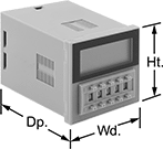
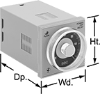
Solid State Versa-Mount Multifunction Timer Relays
Install these relays in a panel cutout or plug them into a relay socket. Unlike mechanical relays, these solid state relays have no moving parts, so they require less maintenance and last longer, are quieter, and switch faster. They give you a variety of timing functions in one relay.
Single-circuit relays give you additional flexibility—they have two types of delayed switch-off (delay-on-break) functions and two types of signal on/off delay functions.
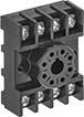
Relay sockets (sold separately) mount to
Mounting brackets (sold separately) are required to mount relays into a panel cutout.

Timer Relays | |||||||||||||
|---|---|---|---|---|---|---|---|---|---|---|---|---|---|
Timing Range | Relay Sockets | ||||||||||||
| No. of Terminals | Input Voltage | Control Current, mA | Timer Relay Function | No. of | Overall | Switching Current @ 240V AC | Ht. | Wd. | Dp. | Each | Each | ||
1 Circuit Controlled with 1 Off (Normally Open) or 1 On (Normally Closed)—SPDT | |||||||||||||
| 11 | 24V AC, 48V AC, 120V AC, 240V AC, 12V DC, 24V DC, 48V DC, 60V DC, 120V DC, 240V DC | 17 | Delayed Start (Delay-on-Make) Interval Switch-On (Single-Shot) Delayed Switch-Off (Delay-on-Break) Repeat Cycle | 7 | 0.1 sec.-999 hrs. | 3A | 1.9" | 1.9" | 2.7" | 0000000 | 0000000 | 0000000 | 000000 |
2 Circuits Controlled with 2 Off (Normally Open) or 2 On (Normally Closed)—DPDT | |||||||||||||
| 8 | 120V AC, 240V AC, 110V DC, 120V DC | 13 | Delayed Start (Delay-on-Make) Interval Switch-On (Single-Shot) Repeat Cycle | 4 | 0.05 sec.-300 hrs. | 5A | 1.9" | 1.9" | 2.3" | 00000000 | 000000 | 0000000 | 0000 |
Mounting Hole | ||||||||||
|---|---|---|---|---|---|---|---|---|---|---|
| Material | Mounting Location | No. of | Ctr.-to-Ctr. | Dia. | Mounting Fasteners Included | Screw Size | Ht. | Wd. | Each | |
| Polycarbonate | Panel | 2 | 3" | 5mm | Yes | M5 | 2.28" | 1.89" | 0000000 | 000000 |
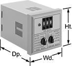
Multifunction Timer Relays
Get a variety of timing functions in a single relay. All relays plug into relay sockets (sold separately) for fast installation and replacement.
Relay socket/panel mount relays require a mounting bracket (sold separately) to mount in a panel cutout.
Relay sockets mount to 35 mm DIN rail (also known as DIN 3 rail) or can be mounted to a flat surface.
Timer Relays | ||||||||||||||
|---|---|---|---|---|---|---|---|---|---|---|---|---|---|---|
Timing Range | Relay Sockets | |||||||||||||
| Number of Terminals | Input Voltage | Control Current, mA | Timer Relay Function | No. of | Overall | Switching Current @ 240V AC | Max. Switching Voltage | Ht. | Wd. | Dp. | Each | Each | ||
2 Circuits Controlled with 2 Off (Normally Open) or 2 On (Normally Closed)—DPDT | ||||||||||||||
Relay Socket/Panel Mounting Location | ||||||||||||||
| 11 | 24V AC, 48V AC, 120V AC, 240V AC, 24V DC, 48V DC, 60V DC, 120V DC, 240V DC | 104 | Delayed Start (Delay-on-Make) Interval Switch-On (Single-Shot) Delayed Switch-Off (Delay-on-Break) Repeat Cycle | 6 | 0.05 sec.-999 hrs. | 10A | 240V AC | 1.9" | 1.9" | 2.8" | 000000 | 0000000 | 0000000 | 000000 |

Mounting Hole | ||||||||||
|---|---|---|---|---|---|---|---|---|---|---|
| Material | Mounting Location | No. of | Ctr.-to-Ctr. | Dia. | Mounting Fasteners Included | Screw Size | Ht. | Wd. | Each | |
| Polycarbonate | Panel | 2 | 3" | 5mm | Yes | M5 | 2.28" | 1.89" | 0000000 | 000000 |
Smart DIN-Rail Mount Multifunction Timer Relays
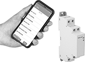

Whether installed in an electrical cabinet or hard-to-reach area, these timer relays are controlled remotely from your smartphone. They connect to your phone via a free downloadable app with NFC (Near Field Communication), so you can set time delay ranges, adjust settings, and save programs. An LED indicator on the relay shows that your switch is on and whether it’s actuated. Mount them directly to 35 mm DIN rail (also known as DIN 3 rail).
Although these relays have 30 different functions, they all fall into 11 categories. Within these categories, you can select different functions to allow you to add a switch, program a delay, or change how the relay responds to a trigger (turning on or off, pausing, or resetting).
Manual Switch Control—Use these functions to turn the relay on and off with a switch.
Fixed On/Off—The on function keeps the relay on whenever input voltage is applied; it will only turn off if the voltage is removed. The off function keeps the relay in an off state, even if input voltage is applied.
Switch-On (Single-Shot)—These functions require a switch to activate the relay, which stays on for the programmed amount of time. For example, lights in a storage room are turned on with a switch and stay on for a set time before turning off.
Delayed Start (Delay-on-Make)—These functions allow you to set how long it takes for the relay to turn on after input voltage is applied. For example, a drill starts pumping lubricant immediately, but it does not start rotating until the set time has elapsed.
Delayed Switch-Off (Delay-on-Break)—These functions use a switch instead of input voltage. When the switch is turned off, the relay remains on for a programmed amount of time before turning off. For example, a projector’s light is turned off with a switch, but its cooling fan continues to run for a set time.
Delayed Switch-On with Delayed Switch-Off—This function uses a switch instead of an input voltage. It allows you to set how long it takes the relay to turn on after a switch is turned on, and how long it will stay on after the switch is turned off. For example, a furnace turns on, but the fan doesn’t start pushing air through the vents until it has been heated. When the furnace turns off, the fan keeps blowing to circulate all the hot air.
Interval—These functions use input voltage to turn on the relay for a programmed amount of time. For example, when a part moving down a conveyor reaches a certain location, a cleaning spray comes on for a set amount of time.
Repeat Cycle—These functions start with an on cycle and then alternate between an on cycle and off cycle of equal durations until input voltage is removed, such as with a flashing light.
Asymmetrical Repeat Cycle—These functions start with an on-cycle and then have an off-cycle, but these cycles have different durations. The cycles repeat until input voltage is removed. For example, a sprinkler system sprays in short bursts followed by longer rest periods, on and off until input voltage is removed.
Switch-On Asymmetrical Repeat Cycle—These functions require a switch to activate the timing function. The input voltage is applied the whole time, and when you turn the switch on, the relay begins with an on-cycle followed by an off-cycle. These cycles have different durations, and they repeat until you turn the switch off. They could be used to turn on a motor or other system for a short period and then turn it off for a longer rest period, repeating that pattern until the switch is turned off.
Star-to-Delta—These functions allow you to set the time delay within the relay's range to switch contacts on a three-phase motor from star to delta configuration. Since star configuration takes less voltage to start than delta, these functions prevent voltage dips that often happen when a motor starts and are gentler on mechanical parts.
![]() For technical drawings and 3-D models, click on a part number.
For technical drawings and 3-D models, click on a part number.
| No. of Terminals | Input Voltage | Control Power, W | Timer Relay Function | O'all Timing Range | Switching Current @ 240V AC | Max. Switching Voltage | Ht. | Wd. | Dp. | Operating System Compatibility | Features | Each | |
1 Circuit Controlled with 1 Off (Normally Open) or 1 On (Normally Closed)—SPDT | |||||||||||||
|---|---|---|---|---|---|---|---|---|---|---|---|---|---|
| 8 | 12V AC, 24V AC, 48V AC, 120V AC, 240V AC, 12V DC, 24V DC, 48V DC, 60V DC, 120V DC, 240V DC | 0.15 | Manual Switch Control Fixed On/Off Switch-On (Single-Shot) Delayed Start (Delay-on-Make) Delayed Switch-Off (Delay-on-Break) Delayed Switch-On with Delayed Switch-Off Interval Repeat Cycle Asymmetrical Repeat Cycle Switch-On Asymmetrical Repeat Cycle | 0.1 sec.-999 days | 8A | 250V AC | 4.1" | 0.7" | 2.5" | Android 5.0 or Later, iOS 14.4 or Later | LED Indicator | 0000000 | 000000 |
2 Circuits Controlled with 2 Off (Normally Open) or 2 On (Normally Closed)—DPDT | |||||||||||||
| 9 | 24V AC, 48V AC, 120V AC, 240V AC, 24V DC, 48V DC, 60V DC, 120V DC, 240V DC | 0.6 | Manual Switch Control Fixed On/Off Switch-On (Single-Shot) Delayed Start (Delay-on-Make) Delayed Switch-Off (Delay-on-Break) Delayed Switch-On with Delayed Switch-Off Interval Repeat Cycle Asymmetrical Repeat Cycle Switch-On Asymmetrical Repeat Cycle Star-to-Delta | 0.1 sec.-999 hrs. | 8A | 250V AC | 3.5" | 0.9" | 2.9" | Android 4.4 or Later, iOS 14.5 or Later | LED Indicator | 0000000 | 00000 |
Solid State Versa-Mount Timer Relays
Mount these timer relays in a panel cutout or plug them into a relay socket for quick installation. Capable of fast switching, they are solid state and have no moving parts, so they require less maintenance, last longer, and are quieter than mechanical relays. Unlike standard relays that switch on and off immediately, timer relays delay before the circuit stops or starts.
Delayed-off relays let you set how long it takes for the relay to turn off after input voltage is removed. For example, a sensor detects when an item has been placed on a conveyor, triggering the relay to start the conveyor belt and a cooling fan. After the item has moved past another sensor, the input voltage is removed to stop the conveyor, while the cooling fan runs for a set time before shutting off.
Relays with a repeat cycle alternate between an on cycle and off cycle of equal durations until input voltage is removed. A common example would be a flashing light.
Relays with an asymmetrical repeat cycle begin in an on state, then alternate between different durations of off and on for as long as input voltage is applied. For example, a heating system starts with an on period, then switches to an off period once the desired temperature is reached.
Relays with a start-off asymmetrical repeat cycle begin in an off state, then alternate between different durations of on and off for as long as input voltage is applied. For example, an irrigation system receives a signal and starts in the off state, allowing water to fill before switching on to start pumping.
Relay sockets (sold separately) mount to 35 mm DIN rail (also known as DIN 3 rail) or can be mounted to a flat surface.
Mounting brackets (sold separately) are required to mount the relay into a panel.
Timer Relays | ||||||||||||
|---|---|---|---|---|---|---|---|---|---|---|---|---|
Timing Range | Relay Sockets | |||||||||||
| Number of Terminals | Input Voltage | Control Current, mA | No. of | Overall | Switching Current @ 240V AC | Ht. | Wd. | Dp. | Each | Each | ||
Delayed Off | ||||||||||||
2 Circuits Controlled with 2 Off (Normally Open) or 2 On (Normally Closed)—DPDT | ||||||||||||
| 8 | 120V AC | 2 | 4 | 0.05 sec.-12 sec. | 5A | 1.9" | 1.9" | 2.74" | 00000000 | 0000000 | 0000000 | 00000 |
| 8 | 120V AC | 2 | 4 | 3 sec.-12 min. | 5A | 1.9" | 1.9" | 2.74" | 00000000 | 000000 | 0000000 | 0000 |
Repeat Cycle | ||||||||||||
2 Circuits Controlled with 2 Off (Normally Open) or 2 On (Normally Closed)—DPDT | ||||||||||||
| 8 | 120V AC, 240V AC, 110V DC, 120V DC | 100 | 4 | 0.05 sec.-300 hrs. | 5A | 1.9" | 1.9" | 3.3" | 00000000 | 000000 | 0000000 | 0000 |
Asymmetrical Repeat Cycle | ||||||||||||
2 Circuits Controlled with 2 Off (Normally Open) or 2 On (Normally Closed)—DPDT | ||||||||||||
| 8 | 24V AC, 48V AC, 12V DC, 24V DC, 48V DC | 83 | 4 | 0.05 sec.-300 hrs. | 5A | 1.9" | 1.9" | 3.3" | 000000000 | 000000 | 0000000 | 0000 |
| 8 | 120V AC, 240V AC, 110V DC, 120V DC | 41 | 4 | 0.05 sec.-300 hrs. | 5A | 1.9" | 1.9" | 3.3" | 000000000 | 000000 | 0000000 | 0000 |
| 11 | 24V AC, 48V AC, 12V DC, 24V DC, 48V DC | 83 | 4 | 0.05 sec.-300 hrs. | 5A | 1.9" | 1.9" | 3.3" | 0000000 | 000000 | 0000000 | 00000 |
| 11 | 120V AC, 240V AC, 110V DC, 120V DC | 41 | 4 | 0.05 sec.-300 hrs. | 5A | 1.9" | 1.9" | 3.3" | 0000000 | 000000 | 0000000 | 00000 |
Start-Off Asymmetrical Repeat Cycle | ||||||||||||
2 Circuits Controlled with 2 Off (Normally Open) or 2 On (Normally Closed)—DPDT | ||||||||||||
| 8 | 24V AC, 48V AC, 12V DC, 24V DC, 48V DC | 83 | 4 | 0.05 sec.-300 hrs. | 5A | 1.9" | 1.9" | 3.3" | 000000000 | 000000 | 0000000 | 0000 |
| 8 | 120V AC, 240V AC, 110V DC, 120V DC | 41 | 4 | 0.05 sec.-300 hrs. | 5A | 1.9" | 1.9" | 3.3" | 000000000 | 000000 | 0000000 | 0000 |
| 11 | 24V AC, 48V AC, 12V DC, 24V DC, 48V DC | 83 | 4 | 0.05 sec.-300 hrs. | 5A | 1.9" | 1.9" | 3.3" | 0000000 | 000000 | 0000000 | 00000 |
| 11 | 120V AC, 240V AC, 110V DC, 120V DC | 41 | 4 | 0.05 sec.-300 hrs. | 5A | 1.9" | 1.9" | 3.3" | 00000000 | 000000 | 0000000 | 00000 |
Mounting Hole | ||||||||||
|---|---|---|---|---|---|---|---|---|---|---|
| Material | Mounting Location | No. of | Ctr.-to-Ctr. | Dia. | Mounting Fasteners Included | Screw Size | Ht. | Wd. | Each | |
| Polycarbonate | Panel | 2 | 3" | 5mm | Yes | M5 | 2.28" | 1.89" | 0000000 | 000000 |
Compact Programmable Logic Controllers
Smaller than other PLCs, these controllers save space in your control cabinet. They combine the functionality of a relay, timer relay, and switch in one unit, so you can program simple automation jobs. All have two types of delayed start (delay-on-make) and two types of delayed switch-off (delay-on-break) timing functions. They have passed strict U.S. and Canadian safety standards, and they’re IP20, which prevents fingers and other objects from making contact with live circuits. Mount them to a 35-mm DIN rail.
Controllers with a display make it easy to monitor or modify your system directly on the unit. Controllers without a display eliminate the risk of accidental adjustments while toggling through information or tampering by unauthorized users.
Program these controllers by connecting them to a computer and installing the required software (sold separately). After the initial programming, these controllers can be updated remotely by a human-machine interface (HMI) or computer.
Add expansion modules to increase the number of inputs and outputs. You can connect up to 11 modules to a controller—for a maximum of 188 inputs and outputs. Choose any modules that support the operating voltage of your controller.
![]() For technical drawings and 3-D models, click on a part number.
For technical drawings and 3-D models, click on a part number.


Digital Inputs | Digital Outputs | ||||||||||
|---|---|---|---|---|---|---|---|---|---|---|---|
| Input Signal Type | Voltage | No. of | Voltage | Current | No. of | Signal Type | Operating Voltage | Communication Protocol | Software Included | Each | |
Controllers with Display | |||||||||||
Eaton Easy E4 Series | |||||||||||
| __ | 100-240V AC 100-240V DC | 8 | 240V AC | 8A | 4 | Relay | 100-240V AC 100-240V DC | Modbus TCP/IP | No | 000000 | 0000000 |
| Digital, Analog | 12V DC 24V AC 24V DC 0-10V DC | 8 (4 can be analog) | 240V AC | 8A | 4 | Relay | 12V DC 24V AC 24V DC | Modbus TCP/IP | No | 000000 | 000000 |
| Digital, Analog | 24V DC 0-10V DC | 8 (4 can be analog) | 24V DC | 0.5A | 4 | Transistor | 24V DC | Modbus TCP/IP | No | 0000000 | 000000 |
Controllers without Display | |||||||||||
Eaton Easy E4 Series | |||||||||||
| __ | 100-240V AC 100-240V DC | 8 | 240V AC | 8A | 4 | Relay | 100-240V AC 100-240V DC | Modbus TCP/IP | No | 0000000 | 000000 |
| Digital, Analog | 12V DC 24V AC 24V DC 0-10V DC | 8 (4 can be analog) | 240V AC | 8A | 4 | Relay | 12V DC 24V AC 24V DC | Modbus TCP/IP | No | 0000000 | 000000 |
| Digital, Analog | 24V DC 0-10V DC | 8 (4 can be analog) | 24V DC | 0.5A | 4 | Transistor | 24V DC | Modbus TCP/IP | No | 0000000 | 000000 |
| Manufacturer Model Number | For Operating System | Media Type | Each | |
For Eaton Easy E4 Series | ||||
|---|---|---|---|---|
| EASYSOFT-SWLIC/EasySoft 7 | Windows 7, Windows 8, Windows 8.1, Windows 10 | Download | 000000 | 000000 |

Inputs | Outputs | |||||||
|---|---|---|---|---|---|---|---|---|
| Voltage | No. of | Voltage | Current | No. of | Signal Type | Operating Voltage | Each | |
For Eaton Easy E4 Series | ||||||||
| 100-240V AC 100-240V DC | 4 | 240V AC | 5A | 4 | Relay | 100-240V AC 100-240V DC | 0000000 | 0000000 |
| 100-240V AC 100-240V DC | 8 | 240V AC | 5A | 8 | Relay | 100-240V AC 100-240V DC | 0000000 | 000000 |
| 12V DC 24V AC 24V DC | 4 | 240V AC | 5A | 4 | Relay | 12V DC 24V AC 24V DC | 0000000 | 000000 |
| 12V DC 24V AC 24V DC | 8 | 240V AC | 5A | 8 | Relay | 12V DC 24V AC 24V DC | 0000000 | 000000 |
| 24V DC | 4 | 24V DC | 0.5A | 4 | Transistor | 24V DC | 0000000 | 000000 |
| 24V DC | 8 | 24V DC | 0.5A | 8 | Transistor | 24V DC | 0000000 | 000000 |

Easy-Program Logic Controllers
Design and operate up to six simultaneous programs without symbols or technical language—the on-screen instructions use simple English. These PLCs combine the functionality of a relay, timer relay, and switch in one unit so you can program complex automation jobs. All have memory backup to retain programming during power outages. Mount to 35-mm DIN rail.
Add expansion modules to increase the number of inputs and outputs. Use either module on its own, or add one of each, but two of the same module won’t work together.
Remote timer panels monitor and adjust up to eight timers while the controller is operating.


Digital Inputs | Digital Outputs | |||||||||||||
|---|---|---|---|---|---|---|---|---|---|---|---|---|---|---|
| Voltage | Current | No. of | Voltage | Current | No. of | Signal Type | Operating Voltage | Wire Connection Type | Terminal Size | Ht. | Wd. | Dp. | Each | |
Controllers with PC Software | ||||||||||||||
| 12-14V DC | 10mA | 6 | 230V AC | 5A | 4 | Relay | 115V AC | Screw Terminals | M3 | 2.9" | 2.2" | 4.3" | 000000 | 0000000 |
Controllers with Hand-Held Programmer | ||||||||||||||
| 12-14V DC | 10mA | 6 | 230V AC | 5A | 4 | Relay | 115V AC | Screw Terminals | M3 | 2.9" | 2.2" | 4.3" | 000000 | 000000 |


Hand-Held IO Link Programmers
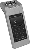
Configure any of your IO Link devices—from sensors to switches—without a PC, outlet, or separate software. Use these programmers to set parameters, check the quality of runs, clone settings for other devices, and more. Whether you’re setting up a device for the first time or adjusting settings, the easy-to-use touchscreen makes for a smooth experience. Since these programmers are powered by a battery and small enough to carry, you can bring them wherever you need.
As soon as you connect your device, these programmers download its IO Device Description (IODD) file. This means you won’t need to manually input device details, saving you time to jump right into programming. Internal storage keeps IODD files and custom settings on hand for you. If you need extra space, insert a microSD card (not included) into these programmers before turning on the connected device.
Plug devices with M8 or M12 connections directly into the sockets on these programmers. If your device has wire leads, use the included adapter.
| Connection Type | Internal Memory Size | Data Connection Type | Features | Environmental Rating | Battery Type | Includes | Specifications Met | Each | |
| A-Code, 3-Pole M8 Socket A-Code, 4-Pole M8 Socket A-Code, 5-Pole M12 Socket | 16 GB | Wi-Fi microSD Card | LED Status Indicator | IP30 | Rechargeable | M12 to 4 Hook Adapter (1 1/2 ft. Lg) USB Charging Cord (1 1/2 ft. Lg) | CE Marked | 0000000 | 000000000 |
IO Link Controllers and Modules

Create a system of sensors and actuators that you can remotely update, view measurements from, and receive error messages in real time. IO Link systems minimize downtime by locating issues such as cut cables or dirty sensors quickly. They send only digital signals to your PLC, regardless of whether your sensors and actuators send digital or analog signals. Because these systems send digital signals, they’re more reliable and less prone to data error and signal loss than analog signals. It also means you don't have to use expensive shielded cables since they resist EMI.
When retrofitting an existing system, you'll need to make sure your PLC can incorporate IO Link. Check with your PLC manufacturer—most have hardware that allows you to upgrade your PLC to run IO Link.
Controllers communicate between your sensors and actuators and your PLC. They are required. Setting memory automatically stores your settings and restores them once your device is back online. This eliminates needing to program a device again when you replace or fix it. Surface mount controllers let you mount controllers on equipment such as tanks and conveyors. By mounting them on your equipment, you save space in your control cabinet. They use M12 connectors. DIN-rail mount controllers are designed to mount inside your control cabinet, so you can access all your process control devices in a central location. They include RJ45 Ethernet ports to support JSON and MQTT IoT (Internet of Things) protocols, allowing you to link the system directly to your web server to upload information to the Cloud. Connect these ports with RJ45 cords.
Protective caps prevent dust and debris from harming M12 connections when they're not in use. They also help maintain IP ratings by covering unused ports. Stainless steel protective caps have a neoprene gasket, which helps maintain IP69K ratings.
IP rated components block out dust and withstand some water, so they do not require an enclosure. Ports that are unused must be capped to maintain their rating. IP66 rated components withstand washdowns. IP67 rated components can be temporarily submerged in water. IP69K rated components hold up to high-pressure and high-temperature washdowns.
Note: Sockets may have extra holes on their face that are not used.
![]() For technical drawings and 3-D models, click on a part number.
For technical drawings and 3-D models, click on a part number.

Input | Output | |||||||||||||||
|---|---|---|---|---|---|---|---|---|---|---|---|---|---|---|---|---|
| Communication Protocol | No. of Device Ports | Total No. of RJ45 Connections | Total No. of M12 Connections | Type | Signal | Voltage | No. of | Type | Signal | Voltage | Current | No. of | Operating Voltage | Specifications Met | Each | |
Surface Mount | ||||||||||||||||
IP66, IP67 | ||||||||||||||||
| IO Link, Ethernet/IP | 4 | __ | 7 | Digital | PNP | 0-30V DC | 8 | Digital | PNP | 30V DC | 0.3A | 4 | 20-30V DC | UL Listed, C-UL Listed, CE Marked | 0000000 | 0000000 |
| IO Link, Ethernet/IP | 8 | __ | 11 | Digital | PNP | 0-30V DC | 16 | Digital | PNP | 30V DC | 0.3A | 8 | 20-30V DC | UL Listed, C-UL Listed, CE Marked | 0000000 | 000000 |
| IO Link, Profinet | 4 | __ | 7 | Digital | PNP | 0-30V DC | 8 | Digital | PNP | 30V DC | 0.3A | 4 | 20-30V DC | UL Listed, C-UL Listed, CE Marked | 0000000 | 000000 |
| IO Link, Profinet | 8 | __ | 11 | Digital | PNP | 0-30V DC | 16 | Digital | PNP | 30V DC | 0.3A | 8 | 20-30V DC | UL Listed, C-UL Listed, CE Marked | 0000000 | 000000 |
IP66, IP67, IP69K | ||||||||||||||||
| IO Link, Ethernet/IP | 4 | __ | 7 | Digital | PNP | 0-30V DC | 8 | Digital | PNP | 30V DC | 0.3A | 4 | 20-30V DC | UL Listed, C-UL Listed, CE Marked | 0000000 | 000000 |
| IO Link, Ethernet/IP | 8 | __ | 11 | Digital | PNP | 0-30V DC | 16 | Digital | PNP | 30V DC | 0.3A | 8 | 20-30V DC | UL Listed, C-UL Listed, CE Marked | 0000000 | 000000 |
| IO Link, Profinet | 4 | __ | 7 | Digital | PNP | 0-30V DC | 8 | Digital | PNP | 30V DC | 0.3A | 4 | 20-30V DC | UL Listed, C-UL Listed, CE Marked | 0000000 | 000000 |
| IO Link, Profinet | 8 | __ | 11 | Digital | PNP | 0-30V DC | 16 | Digital | PNP | 30V DC | 0.3A | 8 | 20-30V DC | UL Listed, C-UL Listed, CE Marked | 0000000 | 000000 |
DIN-Rail Mount | ||||||||||||||||
IP20 | ||||||||||||||||
| IO Link, Ethernet/IP | 8 | 3 | __ | Digital | PNP | 0-30V DC | 8 | Digital | PNP | 30V DC | 0.3A | 8 | 20-30V DC | UL Listed, C-UL Listed, CE Marked | 0000000 | 000000 |
| IO Link, Profinet | 8 | 3 | __ | Digital | PNP | 0-30V DC | 8 | Digital | PNP | 30V DC | 0.3A | 8 | 20-30V DC | UL Listed, C-UL Listed, CE Marked | 0000000 | 000000 |


For Thread | ||||||
|---|---|---|---|---|---|---|
| Size | Location | Material | Temperature Range, °F | Includes | Each | |
For Plugs | ||||||
| M12 | External | Anodized Aluminum | 0° to 220° | Lanyard | 0000000 | 000000 |
| M12 | External | Stainless Steel | 0° to 220° | Lanyard | 0000000 | 00000 |
For Sockets | ||||||
| M12 | Internal | Anodized Aluminum | 0° to 220° | __ | 0000000 | 00000 |
| M12 | Internal | Stainless Steel | 0° to 220° | Lanyard | 0000000 | 00000 |