


Current Relays

Prevent AC current overload in equipment such as motors and heaters.
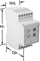
These relays sense current flowing through wires routed through the opening. If the current exceeds a set trip point, the relay trips and starts the adjustable delay timer. After the timer's cycle, the relay cuts power to the equipment to protect against overload. Once current drops below the trip point, the relay allows power to flow again to the equipment.
To determine the current trip range for more than one wire, divide the listed trip range by the number of wires passed through the opening.
| Current Trip Range for One Wire, A | Switch Industry Designation | Resistive Load | Delay Time Range | For Max. Wire Dia. | Ht. | Wd. | Dp. | Input AC Voltage | Wire Connection | Specifications Met | Mount Type | Fasteners Included | Mounting Hole Dia. | No. of Mounting Holes | Each | |
Measures AC Current | ||||||||||||||||
|---|---|---|---|---|---|---|---|---|---|---|---|---|---|---|---|---|
| 0.1-1 | SPDT | 10 A @ 240 V AC | 0.5-6 sec. | 0.5" | 2.13" | 3.5" | 2.5" | 120 | 1/4" Quick-Disconnect Terminals | UL Recognized Component | Screw On | No | 0.19" | 2 | 00000000 | 0000000 |
| 1-10 | SPDT | 10 A @ 240 V AC | 0.5-6 sec. | 0.5" | 2.13" | 3.5" | 2.5" | 120 | 1/4" Quick-Disconnect Terminals | UL Recognized Component, C-UL Recognized Component | Screw On | No | 0.19" | 2 | 00000000 | 000000 |
| 3-30 | SPDT | 10 A @ 240 V AC | 0.5-6 sec. | 0.5" | 2.13" | 3.5" | 2.5" | 120 | 1/4" Quick-Disconnect Terminals | UL Recognized Component, C-UL Recognized Component | Screw On | No | 0.19" | 2 | 00000000 | 000000 |
| 6-60 | SPDT | 10 A @ 240 V AC | 0.5-6 sec. | 0.5" | 2.13" | 3.5" | 2.5" | 120 | 1/4" Quick-Disconnect Terminals | UL Recognized Component, C-UL Recognized Component | Screw On | No | 0.19" | 2 | 00000000 | 000000 |
| 10-100 | SPDT | 10 A @ 240 V AC | 0.5-6 sec. | 0.5" | 2.13" | 3.5" | 2.5" | 120 | 1/4" Quick-Disconnect Terminals | UL Recognized Component, C-UL Recognized Component | Screw On | No | 0.19" | 2 | 00000000 | 000000 |
Current-Monitoring Relays
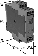
Protect electrical equipment from overcurrent and undercurrent damage—these relays continuously monitor current flow. When current is outside a set range, they trip and cut power to prevent overheating, fire hazards, and stalling. Rated IP20, these relays have recessed terminals that keep fingers and other objects from touching live circuits. Mount them on a 35 mm DIN rail (also known as DIN 3 rail) for fast installation.
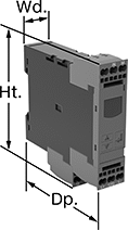
Relays with spring-clamp terminals connect and disconnect to wire without screws. Because there’s no screw, these connections are less likely to loosen over time, even in high-vibration environments.
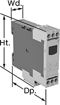
Relays with IO link can be programmed, monitored, and reset remotely by connecting them to a programmable logic controller (PLC), human-machine interface (HMI), or computer. If you want to program them locally, they have a keypad.
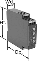
Relays with knob adjustments have knobs right on the front where you can set your trip current. You can see that they're wired correctly and when they're actuated based on the LED indicators.
![]() For technical drawings and 3-D models, click on a part number.
For technical drawings and 3-D models, click on a part number.
Trip Current | |||||||||||||||
|---|---|---|---|---|---|---|---|---|---|---|---|---|---|---|---|
| No. of Terminals | Input Voltage | Trip Current Setting | Min. | Max. | Trip Time, sec. | Reset Type | Switching Current @ Voltage | Max. Switching Voltage | Adjustment Style | Ht. | Wd. | Dp. | Display Type | Each | |
Screw Terminals | |||||||||||||||
1 Off (Normally Open) or 1 On (Normally Closed)—SPDT | |||||||||||||||
| 9 | 24V AC, 24V DC | 0.1-1A, 0.5-5A, 0.8-8A | __ | __ | 0.1-30 | Automatic, Manual | 5 A @ 240 V AC 5 A @ 30 V DC | 250V AC 30V DC | Knob | 3.5" | 0.9" | 3.9" | __ | 0000000 | 0000000 |
| 9 | 120V AC, 240V AC | 0.1-1A, 0.5-5A, 0.8-8A | __ | __ | 0.1-30 | Automatic, Manual | 5 A @ 240 V AC 5 A @ 30 V DC | 250V AC 30V DC | Knob | 3.5" | 0.9" | 3.9" | __ | 0000000 | 000000 |
Screw Terminals with IO Link | |||||||||||||||
1 Off (Normally Open) or 1 On (Normally Closed)—SPDT | |||||||||||||||
| 9 | 24V DC | __ | 0.05A | 10A | 0-999 | Automatic | 1 A @ 24 V DC 3 A @ 240 V AC | 400V AC 250V DC | External Controller, Keypad | 3.6" | 0.9" | 3.4" | LCD | 0000000 | 000000 |
Spring-Clamp Terminals with IO Link | |||||||||||||||
1 Off (Normally Open) or 1 On (Normally Closed)—SPDT | |||||||||||||||
| 9 | 24V DC | __ | 0.05A | 10A | 0-999 | Automatic | 1 A @ 24 V DC 3 A @ 240 V AC | 400V AC 250V DC | External Controller, Keypad | 3.8" | 0.9" | 3.4" | LCD | 0000000 | 000000 |
Ground-Fault Monitoring Relays
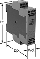
Detect and mitigate ground faults to prevent harm to equipment, circuits, and people. These relays monitor the differential between incoming and outgoing current, also known as residual current. When the balance is off, they trip and cut power to the circuit. These relays are highly sensitive, so you can trust them to de-energize faulty circuits before a minor issue becomes a major one. Rated IP20, they have recessed terminals that keep fingers and other objects from touching live circuits. Mount them on 35 mm DIN rail (also known as DIN 3 rail) for fast installation.
These relays require a current-indicating ring (sold separately) to operate. Choose a ring that is large enough for your lines to pass through. Feed the lines of the circuit through the center of the ring and connect the indicating ring output to the relay.
Relays with spring-clamp terminals connect and disconnect to wire without screws. Because they don’t have screws, there’s less of a risk that they will loosen over time, even when they’re under vibration.
Relays with IO link can be programmed, monitored, and reset remotely by connecting them to a programmable logic controller (PLC), human-machine interface (HMI), or computer. If you want to program them locally, they have a keypad.
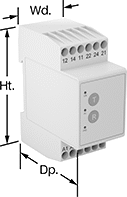
Relays with knob adjustments have knobs right on the front where you can set your trip current.
Relays with an LED indicator show the status of your relay, so you know it is wired correctly and when it is actuated.
![]() For technical drawings and 3-D models, click on a part number.
For technical drawings and 3-D models, click on a part number.
Trip Current | ||||||||||||||
|---|---|---|---|---|---|---|---|---|---|---|---|---|---|---|
| No. of Terminals | Input Voltage | Trip Current Setting | Min. | Max. | Trip Time, sec. | Switching Current @ Voltage | Max. Switching Voltage | Adjustment Style | Ht. | Wd. | Dp. | Features | Each | |
Screw Terminals | ||||||||||||||
2 Off (Normally Open) or 2 On (Normally Closed)—DPDT | ||||||||||||||
| 12 | 24V AC, 48V AC, 120V AC, 240V AC | 0.03A | __ | __ | 0 | 5 A @ 240 V AC 5 A @ 24 V DC | 250V AC 24V DC | __ | 3.2" | 1.4" | 2.6" | LED Indicator | 00000000 | 0000000 |
| 12 | 24V AC, 48V AC, 120V AC, 240V AC | 0.3A | __ | __ | 0 | 5 A @ 240 V AC 5 A @ 24 V DC | 250V AC 24V DC | __ | 3.2" | 1.4" | 2.6" | LED Indicator | 00000000 | 000000 |
| 12 | 24V AC, 48V AC, 120V AC, 240V AC | __ | 0.3A | 30A | 0-5 | 5 A @ 240 V AC 5 A @ 24 V DC | 250V AC 24V DC | Knob | 3.2" | 1.4" | 2.8" | LED Indicator | 00000000 | 000000 |
| 12 | 24V AC, 48V AC, 120V AC, 240V AC | __ | 0.03A | 5A | 0-5 | 5 A @ 240 V AC 5 A @ 24 V DC | 250V AC 24V DC | Knob | 3.2" | 1.4" | 2.8" | LED Indicator | 00000000 | 000000 |
Screw Terminals with IO Link | ||||||||||||||
2 Off (Normally Open) or 2 On (Normally Closed)—DPDT | ||||||||||||||
| 12 | 24V DC | __ | 0.03A | 40A | 0-999 | 3 A @ 240 V AC 1 A @ 24 V DC | 400V AC 250V DC | Keypad, External Controller | 4" | 0.9" | 3.6" | Remote Reset | 00000000 | 000000 |
Spring-Clamp Terminals with IO Link | ||||||||||||||
2 Off (Normally Open) or 2 On (Normally Closed)—DPDT | ||||||||||||||
| 12 | 24V DC | __ | 0.03A | 40A | 0-999 | 3 A @ 240 V AC 1 A @ 24 V DC | 400V AC 250V DC | Keypad, External Controller | 4.1" | 0.9" | 3.6" | Remote Reset | 00000000 | 000000 |
