


How to Identify and Measure Fittings
Pipe size is an industry designation, not the actual size. View information about how to measure threaded and unthreaded pipe and pipe fittings.
More
About Gas Regulators
More
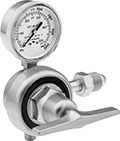
Tank-Mount Pressure-Regulating Valves with Flowmeter for Inert Gas
- For Use With: See Table
- Temperature Range: -20° to 120° F
Commonly used in TIG welding where gas flow/coverage is a concern, these valves measure the gas flow rate in addition to regulating pressure. They automatically reduce a high inlet pressure from compressed gas tanks to a lower, stable outlet pressure. All have Compressed Gas Association (CGA) numbered inlet fittings for secure connections to compressed gas tanks. Choose a valve with the same CGA number as your tank and other system components. Valves have a gauge to monitor the outlet flow rate and a second gauge to monitor inlet pressure from the tank. They are single stage and reduce pressure in one step, which causes the outlet pressure to fluctuate slightly as you empty the tank.


Inlet | Outlet | Material | |||||||||||||
|---|---|---|---|---|---|---|---|---|---|---|---|---|---|---|---|
| CGA Number | Location | Thread Direction | Pressure Gauge Range, psi | Stage | Thread Size | Location | Thread Direction | Flow Range, scfh | Flow Gauge Included | Body | Seal | Diaphragm | Includes | Each | |
UNF Female Outlet × NGO Male Inlet | |||||||||||||||
| CGA 580 | Side | Right Hand | 0 to 4,000 | Single | 5/8"-18 | Side | Right Hand | 0 to 60 | Yes | Brass | PTFE | Neoprene | __ | 0000000 | 0000000 |
| CGA 580 | Side | Right Hand | 0 to 4,000 | Single | 5/8"-18 | Side | Right Hand | 0 to 60 | Yes | Brass | PTFE | Neoprene | 10-ft. long, 3/16" dia. hose with 5/8"-18 male fittings on both ends | 0000000 | 000000 |
| CGA 580 | Side | Right Hand | 0 to 4,000 | Single | 5/8"-18 | Side | Right Hand | 0 to 100 | Yes | Brass | PTFE | Neoprene | __ | 0000000 | 000000 |
Easy-Read Tank-Mount Pressure-Regulating
Valves with Flowmeter for Inert Gas


Flowmeters let you see the gas flow rate from a distance. These valves automatically reduce a high inlet pressure from compressed gas tanks to a lower, stable outlet pressure. All have Compressed Gas Association (CGA) numbered inlet fittings for secure connections to compressed gas tanks. Choose a valve with the same CGA number as your tank and other system components. They have a gauge for monitoring inlet pressure from the tank.
Single-stage valves reduce pressure in one step, which causes the outlet pressure to fluctuate slightly as you empty the tank. They’re best for applications where a constant outlet pressure isn’t critical.
Two-stage valves progressively reduce pressure over two steps for more consistent outlet pressure at all times. They’re often used in applications that require a constant outlet pressure regardless of the tank level.
Valves with one flowmeter are for one piece of equipment on a tank. The flowmeter has a single scale.
Valve with two flowmeters lets you simultaneously run two pieces of equipment from one tank. Both flowmeters have a dual scale.
Adapters (sold separately) change 5/8"-18 outlets to 9/16"-18 male connections, and vice versa.
Inlet | Outlet | Material | ||||||||||||
|---|---|---|---|---|---|---|---|---|---|---|---|---|---|---|
| CGA Number | Location | Thread Direction | Pressure Gauge Range, psi | Stage | Thread Size | Location | Thread Direction | Flow Range, scfh | Number of Flowmeters | Body | Seal | Diaphragm | Each | |
UNF Female Outlet × NGO Male Inlet | ||||||||||||||
| CGA 580 | Side | Right Hand | 0 to 4,000 | Single | 5/8"-18 | Side | Right Hand | 0 to 70 | 1 | Brass | PTFE | Neoprene | 00000000 | 0000000 |
| Optional Adapter | 00000000 | Each | 000000 |
Inlet | Outlet | Material | ||||||||||||
|---|---|---|---|---|---|---|---|---|---|---|---|---|---|---|
| CGA Number | Location | Thread Direction | Pressure Gauge Range, psi | Stage | Thread Size | Location | Thread Direction | Flow Range, scfh | Number of Flowmeters | Body | Seal | Diaphragm | Each | |
UNF Female Outlet × NGO Male Inlet | ||||||||||||||
| CGA 580 | Side | Right Hand | 0 to 3,000 | Single | 5/8"-18 | Side | Right Hand | 0 to 70 (Argon), 0 to 70 (Argon/Carbon Dioxide Blend) | 1 | Brass | PTFE | Neoprene | 0000000 | 0000000 |
| Optional Adapter | 00000000 | Each | 000000 |
Inlet | Outlet | Material | ||||||||||||
|---|---|---|---|---|---|---|---|---|---|---|---|---|---|---|
| CGA Number | Location | Thread Direction | Pressure Gauge Range, psi | Stage | Thread Size | Location | Thread Direction | Flow Range, scfh | Number of Flowmeters | Body | Seal | Diaphragm | Each | |
UNF Female Outlet × NGO Male Inlet | ||||||||||||||
| CGA 580 | Side | Right Hand | 0 to 3,000 | Two | 5/8"-18 | Side | Right Hand | 0 to 40 (Argon), 0 to 40 (Argon/Carbon Dioxide Blend), 0 to 150 (Helium) to150 | 1 | Brass | PTFE | Neoprene | 000000000 | 0000000 |
| Optional Adapter | 00000000 | Each | 000000 |
Inlet | Outlet | Material | ||||||||||||
|---|---|---|---|---|---|---|---|---|---|---|---|---|---|---|
| CGA Number | Location | Thread Direction | Pressure Gauge Range, psi | Stage | Thread Size | Location | Thread Direction | Flow Range, scfh | Number of Flowmeters | Body | Seal | Diaphragm | Each | |
UNF Female Outlet × NGO Male Inlet | ||||||||||||||
| CGA 580 | Side | Right Hand | 0 to 4,000 | Single | 5/8"-18 | Side | Right Hand | 0 to 60 (Argon), 0 to 60 (Argon/Carbon Dioxide Blend), 0 to 50 (Carbon Dioxide), 0 to 160 (Helium) | 1 | Brass | Buna-N | Brass | 000000000 | 0000000 |
| Optional Adapter | 00000000 | Each | 000000 |
Inlet | Outlet | Material | ||||||||||||
|---|---|---|---|---|---|---|---|---|---|---|---|---|---|---|
| CGA Number | Location | Thread Direction | Pressure Gauge Range, psi | Stage | Thread Size | Location | Thread Direction | Flow Range, scfh | Number of Flowmeters | Body | Seal | Diaphragm | Each | |
UNF Female Outlet × NGO Male Inlet | ||||||||||||||
| CGA 580 | Side | Right Hand | 0 to 3,000 | Two | 5/8"-18 | Side | Right Hand | 0 to 18 (Argon), 0 to 50 (Helium) | 1 | Brass | PTFE | Neoprene | 000000000 | 0000000 |
| CGA 580 | Side | Right Hand | 0 to 3,000 | Two | 5/8"-18 | Side | Right Hand | 0 to 65 (Argon), 0 to 200 (Helium) | 1 | Brass | PTFE | Neoprene | 000000000 | 000000 |
| CGA 580 | Side | Right Hand | 0 to 4,000 | Single | 5/8"-18 | Side | Right Hand | 0 to 45 (Argon), 0 to 140 (Helium) | 1 | Brass | PTFE | Neoprene | 00000000 | 000000 |
| CGA 580 | Side | Right Hand | 0 to 4,000 | Single | 5/8"-18 | Side | Right Hand | 0 to 45 (Argon), 0 to 140 (Helium) | 2 | Brass | PTFE | Neoprene | 0000000 | 000000 |
| Optional Adapter | 00000000 | Each | 000000 |
Inlet | Outlet | Material | ||||||||||||
|---|---|---|---|---|---|---|---|---|---|---|---|---|---|---|
| CGA Number | Location | Thread Direction | Pressure Gauge Range, psi | Stage | Thread Size | Location | Thread Direction | Flow Range, scfh | Number of Flowmeters | Body | Seal | Diaphragm | Each | |
UNF Female Outlet × NGO Male Inlet | ||||||||||||||
| CGA 580 | Side | Right Hand | 0 to 4,000 | Single | 5/8"-18 | Side | Right Hand | 0 to 100 (Helium), 0 to 140 (Hydrogen) | 1 | Brass | PTFE | Neoprene | 000000000 | 0000000 |
| Optional Adapter | 00000000 | Each | 000000 |
Inlet | Outlet | Material | ||||||||||||
|---|---|---|---|---|---|---|---|---|---|---|---|---|---|---|
| CGA Number | Location | Thread Direction | Pressure Gauge Range, psi | Stage | Thread Size | Location | Thread Direction | Flow Range, scfh | Number of Flowmeters | Body | Seal | Diaphragm | Each | |
UNF Female Outlet × NGO Male Inlet | ||||||||||||||
| CGA 580 | Side | Right Hand | 0 to 4,000 | Single | 5/8"-18 | Side | Right Hand | 0 to 100 | 1 | Brass | PTFE | Neoprene | 00000000 | 0000000 |
| Optional Adapter | 00000000 | Each | 000000 |
Tank-Mount Pressure-Regulating Valves for Air and Inert Gas
- For Use With: See Table
- Temperature Range: -20° to 120° F
These valves automatically reduce a high inlet pressure from compressed gas tanks to a lower, stable outlet pressure. All have Compressed Gas Association (CGA) numbered inlet fittings for secure connections to compressed gas tanks. Choose a valve with the same CGA number as your tank and other system components. Valves have a gauge to monitor outlet pressure and a gauge to monitor inlet pressure from the tank.
Choose a valve with a maximum outlet pressure that’s approximately twice your application’s normal operating pressure. Your operating pressure should never exceed 75% of the valve’s maximum outlet pressure.
Single-stage valves reduce pressure in one step, which causes the outlet pressure to fluctuate slightly as you empty the tank. They’re best for applications where a constant outlet pressure isn’t critical.
Two-stage valves progressively reduce pressure over two steps for more consistent outlet pressure at all times. They’re often used in applications that require a constant outlet pressure regardless of the tank level.
Valves with a brass body have a longer service life than valves with a brass and steel body.
Valves with a stainless steel diaphragm can withstand harsh environments.
Valves with flared tube outlet fittings form a tight seal on metal tubing.


Inlet | Outlet | Material | ||||||||||
|---|---|---|---|---|---|---|---|---|---|---|---|---|
| CGA Number | Location | Thread Direction | Pressure Gauge Range, psi | Location | Thread Direction | Pressure Range, psi | Pressure Adjustment Method | Body | Seal | Diaphragm | Each | |
For Use With Argon, Helium, and Nitrogen | ||||||||||||
37° Flared UNF Male Outlet × NGO Male Inlet | ||||||||||||
| CGA 580 | Side | Right Hand | 0 to 4,000 | Side | Right Hand | 10 to 200 | __ | Brass | Polyurethane | Neoprene/Nylon | 00000000 | 0000000 |
45° Flared UN/UNF (SAE 45°) Male Outlet × NGO Male Inlet | ||||||||||||
| CGA 580 | Side | Right Hand | 0 to 4,000 | Side | Right Hand | 0 to 250 | T-Handle | Brass | PTFE | Neoprene | 00000000 | 000000 |
| CGA 580 | Side | Right Hand | 0 to 4,000 | Side | Right Hand | 0 to 500 | T-Handle | Brass | PTFE | Neoprene | 00000000 | 000000 |
5/8"-18 UNF Female Outlet × NGO Male Inlet | ||||||||||||
| CGA 580 | Side | Right Hand | 0 to 4,000 | Side | Right Hand | 0 to 125 | T-Handle | Brass | PTFE | Stainless Steel | 00000000 | 000000 |
9/16"-18 UNF Male Outlet × NGO Male Inlet | ||||||||||||
| CGA 580 | Side | Right Hand | 0 to 4,000 | Side | Right Hand | 0 to 50 | T-Handle | Brass | PTFE | Neoprene | 00000000 | 000000 |
| CGA 580 | Side | Right Hand | 0 to 4,000 | Side | Right Hand | 0 to 125 | T-Handle | Brass | PTFE | Rubber | 0000000 | 000000 |
| CGA 580 | Side | Right Hand | 0 to 4,000 | Side | Right Hand | 0 to 145 | Knob | Brass/Steel | PTFE | Rubber | 0000000 | 000000 |
| CGA 580 | Side | Right Hand | 0 to 4,000 | Side | Right Hand | 0 to 200 | T-Handle | Brass | PTFE | Rubber | 0000000 | 000000 |

Inlet | Outlet | Material | ||||||||||
|---|---|---|---|---|---|---|---|---|---|---|---|---|
| CGA Number | Location | Thread Direction | Pressure Gauge Range, psi | Location | Thread Direction | Pressure Range, psi | Pressure Adjustment Method | Body | Seal | Diaphragm | Each | |
For Use With Argon, Helium, and Nitrogen | ||||||||||||
1/4 NPT Female Outlet × NGO Male Inlet | ||||||||||||
| CGA 580 | Side | Right Hand | 0 to 4,000 | Side | Right Hand | 0 to 250 | T-Handle | Brass | PTFE | Neoprene | 00000000 | 0000000 |
| CGA 580 | Side | Right Hand | 0 to 4,000 | Side | Right Hand | 0 to 250 | T-Handle | Brass | PTFE | Stainless Steel | 00000000 | 000000 |
5/8"-18 UNF Female Outlet × NGO Male Inlet | ||||||||||||
| CGA 580 | Side | Right Hand | 0 to 4,000 | Side | Right Hand | 0 to 50 | T-Handle | Brass | PTFE | Neoprene | 00000000 | 000000 |
| CGA 580 | Side | Right Hand | 0 to 4,000 | Side | Right Hand | 0 to 50 | T-Handle | Brass | PTFE | Stainless Steel | 0000000 | 000000 |
| CGA 580 | Side | Right Hand | 0 to 4,000 | Side | Right Hand | 0 to 125 | T-Handle | Brass | PTFE | Stainless Steel | 0000000 | 000000 |
| CGA 580 | Side | Right Hand | 0 to 4,000 | Side | Right Hand | 0 to 125 | T-Handle | Brass/Steel | PTFE | Rubber | 0000000 | 000000 |
Tank-Mount High-Pressure-Regulating Valves for Air and Inert Gas
- For Use With: See Table
- Temperature Range: -20° to 120° F
Often used for pressure-vessel testing and other high-pressure applications, these valves can handle at least seven times the outlet pressure of standard tank-mount pressure-regulating valves. They automatically reduce a high inlet pressure from compressed gas tanks to a lower, stable outlet pressure. All have Compressed Gas Association (CGA) numbered inlet fittings for secure connections to compressed gas tanks. Choose a valve with the same CGA number as your tank and other system components. Outlet fittings are Swagelok® for a leak-free seal around hard metal tubing in high-pressure lines. Also known as instrumentation fittings, Swagelok® fittings are compatible with Parker A-Lok, Gyrolok, Bilok, and Tylok fittings. Valves have a gauge to monitor outlet pressure and a gauge to monitor inlet pressure from the tank. They are single stage and reduce pressure in one step, which causes the outlet pressure to fluctuate slightly as you empty the tank.
Choose a valve with a maximum outlet pressure that’s approximately twice your application’s normal operating pressure. Your operating pressure should never exceed 75% of the valve’s maximum outlet pressure.

Inlet | Outlet | Material | ||||||||||
|---|---|---|---|---|---|---|---|---|---|---|---|---|
| CGA Number | Location | Thread Direction | Pressure Gauge Range, psi | Stage | For Tube OD | Location | Pressure Range, psi | Shape | Body | Seal | Each | |
NGO Male Inlet × Swagelok® Female Outlet | ||||||||||||
| CGA 580 | Side | Right Hand | 0 to 4,000 | Single | 1/4" | Bottom | 200 to 3,000 | 90° Elbow | Brass | PCTFE | 0000000 | 0000000 |
High-Purity Tank-Mount Pressure-Regulating Valves for Inert Gas
- For Use With: See Table
- Temperature Range: -20° to 120° F
Reduce contaminants in research sample systems, emission monitoring systems, chromatography, and other high-purity applications that use argon, helium, nitrogen, or carbon dioxide. These valves have a 316 stainless steel and brass body with a smooth finish to reduce dust collection and internal components designed to protect the seal and diaphragm from contamination. They automatically reduce a high inlet pressure from compressed gas tanks to a lower, stable outlet pressure. All have Compressed Gas Association (CGA) numbered inlet fittings for secure connections to compressed gas tanks. Choose a valve with the same CGA number as your tank and other system components. Outlet fittings are Swagelok® for a leak-free seal around hard metal tubing in high-pressure lines. Also known as instrumentation fittings, Swagelok® fittings are compatible with Parker A-Lok, Gyrolok, Bilok, and Tylok fittings. Valves have a gauge to monitor outlet pressure and a gauge to monitor inlet pressure from the tank.
Choose a valve with a maximum outlet pressure that’s approximately twice your application’s normal operating pressure. Your operating pressure should never exceed 75% of the valve’s maximum outlet pressure.
Single-stage valves reduce pressure in one step, which causes the outlet pressure to fluctuate slightly as you empty the tank. They’re best for applications where a constant outlet pressure isn’t critical.
Two-stage valves progressively reduce pressure over two steps for more consistent outlet pressure at all times. They’re often used in applications that require a constant outlet pressure regardless of the tank level.
Chrome-plated valves add a layer of corrosion resistance.


Inlet | Outlet | |||||||||
|---|---|---|---|---|---|---|---|---|---|---|
| CGA Number | Location | Thread Direction | Pressure Gauge Range, psi | Stage | For Tube OD | Location | Pressure Range, psi | Pressure Adjustment Method | Each | |
Swagelok® Female Outlet × NGO Male Inlet | ||||||||||
Brass Body—316 Stainless Steel Diaphragm and PTFE Seal | ||||||||||
| CGA 580 | Side | Right Hand | 0 to 4,000 | Single | 1/4" | Side | 0 to 15 | Knob | 0000000 | 0000000 |
| CGA 580 | Side | Right Hand | 0 to 4,000 | Single | 1/4" | Side | 0 to 125 | Knob | 0000000 | 000000 |
| CGA 580 | Side | Right Hand | 0 to 4,000 | Single | 1/4" | Side | 0 to 500 | Knob | 0000000 | 000000 |
| CGA 580 | Side | Right Hand | 0 to 4,000 | Two | 1/4" | Side | 0 to 15 | Knob | 0000000 | 000000 |
| CGA 580 | Side | Right Hand | 0 to 4,000 | Two | 1/4" | Side | 0 to 50 | Knob | 0000000 | 000000 |
| CGA 580 | Side | Right Hand | 0 to 4,000 | Two | 1/4" | Side | 0 to 125 | Knob | 0000000 | 000000 |
| CGA 580 | Side | Right Hand | 0 to 4,000 | Two | 1/4" | Side | 0 to 250 | Knob | 0000000 | 000000 |
Chrome-Plated Brass Body—316 Stainless Steel Diaphragm and PTFE Seal | ||||||||||
| CGA 580 | Side | Right Hand | 0 to 4,000 | Two | 1/4" | Side | 0 to 50 | Knob | 0000000 | 000000 |
Tank-Mount Pressure-Regulating Valves for Moisture Removal

- For Use With: Nitrogen
- Temperature Range: 32° to 120° F
Designed for nitrogen gas purging in air conditioning, refrigeration, and plumbing systems, these valves automatically reduce a high inlet pressure to a lower, stable outlet pressure. They have Compressed Gas Association (CGA) numbered inlet fittings for secure connections to compressed gas tanks. Choose a valve with the same CGA number as your tank and other system components. Valves have 45° flared tube outlet fittings for a tight seal on metal tubing. They come with a gauge to monitor inlet pressure from the tank. They are single stage and reduce pressure in one step, which causes the outlet pressure to fluctuate slightly as you empty the tank.
Choose a valve with a maximum outlet pressure that’s approximately twice your application’s normal operating pressure. Your operating pressure should never exceed 75% of the valve’s maximum outlet pressure.
Inlet | Outlet | |||||||||||
|---|---|---|---|---|---|---|---|---|---|---|---|---|
| CGA Number | Location | Thread Direction | Pressure Gauge Range, psi | Stage | For Tube OD | Location | Thread Direction | Purging Flow Range, cfh | Brazing Flow Range, cfh | Testing Pressure Range, psi | Each | |
NGO Male Inlet × 45° Flared UN/UNF (SAE 45°) Male Outlet with 7/16"-20 End | ||||||||||||
Brass Body—PTFE Seal | ||||||||||||
| CGA 580 | Side | Right Hand | 0 to 3,000 | Single | 1/4" | Side | Right Hand | 25 to 35 | 3 to 6 | 0 to 500 | 00000000 | 0000000 |
Tank-Mount Pressure-Regulating Valves for Cryogenic Cylinders
- For Use With: See Table
- Temperature Range: -20° to 120° F
Automatically reduce a high inlet pressure from compressed gas tanks to a lower, stable outlet pressure. These valves can remove gases from liquid cryogenic cylinders. They have Compressed Gas Association (CGA) numbered inlet fittings for secure connections to compressed gas tanks. Choose a valve with the same CGA number as your tank and other system components. Valves come with a gauge to monitor outlet pressure. They are single stage and reduce pressure in one step, which causes the outlet pressure to fluctuate slightly as you empty the tank.
Choose a valve with a maximum outlet pressure that’s approximately twice your application’s normal operating pressure. Your operating pressure should never exceed 75% of the valve’s maximum outlet pressure.
Inlet | Outlet | ||||||||||
|---|---|---|---|---|---|---|---|---|---|---|---|
| For Use With | CGA Number | Location | Thread Direction | Stage | Thread Size | Location | Thread Direction | Pressure Range, psi | Pressure Adjustment Method | Each | |
UNF Male Outlet × NGO Male Inlet | |||||||||||
Brass Body—Stainless Steel Diaphragm and PTFE Seal | |||||||||||
| Argon, Nitrogen | CGA 580 | Side | Right Hand | Single | 9/16"-18 | Bottom | Right Hand | 0 to 350 | T-Handle | 0000000 | 0000000 |
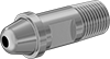
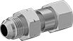
High-Pressure Nipples for Compressed Gas
Commonly used in high-pressure welding applications, these nipples connect your tank to the inlet of a pressure regulator. One side has a threaded pipe end and the other side has a rounded end that sits inside a threaded nut (sold separately) so you can make a threaded connection.
Brass nipples have good corrosion resistance and are softer than 316 stainless steel nipples, so they're easier to thread together. Chrome-plated brass nipples have better corrosion and wear resistance than unplated brass nipples and have a bright, shiny appearance.
Nipples that tighten by hand should be paired with a nut with a plastic grip.
![]() For technical drawings and 3-D models, click on a part number.
For technical drawings and 3-D models, click on a part number.
- Maximum Pressure: See table
- Maximum Temperature: 120° F
Regulator Connection | ||||||
|---|---|---|---|---|---|---|
| For Number (Max. Pressure) | Pipe Size | Thread Type | Lg. | For Use With | Each | |
Brass—Tighten With Wrench | ||||||
| CGA 500, 580, 590 (3,000 psi @ 72° F); CGA 510 (500 psi @ 72° F) | 1/4 | NPT | 2 1/2" | Acetylene, Argon, Butane, Cyclopropane, Dimethyl Ether, Ethylene Oxide, Helium, Isobutane, Krypton, Medical Gas Mixtures, Methane, Methyl Chloride, Natural Gas, Neon, Nitrogen, Propane, Propylene, Sulfur Hexafluoride, Vinyl Chloride, Vinyl Bromide, Xenon | 000000000 | 00000 |
| CGA 500, 580, 590 (3,000 psi @ 72° F); CGA 510 (500 psi @ 72° F) | 1/4 | NPT | 3" | Acetylene, Argon, Butane, Cyclopropane, Dimethyl Ether, Ethylene Oxide, Helium, Isobutane, Krypton, Medical Gas Mixtures, Methane, Methyl Chloride, Natural Gas, Neon, Nitrogen, Propane, Propylene, Sulfur Hexafluoride, Vinyl Chloride, Vinyl Bromide, Xenon | 000000000 | 0000 |
| CGA 500, 580, 590 (3,000 psi @ 72° F); CGA 510 (500 psi @ 72° F) | 1/4 | NPT | 3 1/2" | Acetylene, Argon, Butane, Cyclopropane, Dimethyl Ether, Ethylene Oxide, Helium, Isobutane, Krypton, Medical Gas Mixtures, Methane, Methyl Chloride, Natural Gas, Neon, Nitrogen, Propane, Propylene, Sulfur Hexafluoride, Vinyl Chloride, Vinyl Bromide, Xenon | 000000000 | 0000 |
Brass—Tighten By Hand | ||||||
| CGA 500, 580, 590 (3,000 psi @ 72° F); CGA 510 (500 psi @ 72° F) | 1/4 | NPT | 2 1/2" | Acetylene, Argon, Butane, Cyclopropane, Dimethyl Ether, Ethylene Oxide, Helium, Isobutane, Krypton, Medical Gas Mixtures, Methane, Methyl Chloride, Natural Gas, Neon, Nitrogen, Propane, Propylene, Sulfur Hexafluoride, Vinyl Chloride, Vinyl Bromide, Xenon | 0000000 | 00000 |
| CGA 500, 580, 590 (3,000 psi @ 72° F); CGA 510 (500 psi @ 72° F) | 1/4 | NPT | 3" | Acetylene, Argon, Butane, Cyclopropane, Dimethyl Ether, Ethylene Oxide, Helium, Isobutane, Krypton, Medical Gas Mixtures, Methane, Methyl Chloride, Natural Gas, Neon, Nitrogen, Propane, Propylene, Sulfur Hexafluoride, Vinyl Chloride, Vinyl Bromide, Xenon | 0000000 | 00000 |
| CGA 510 (500 psi @ 72° F); CGA 580, 590 (3,000 psi @ 72° F) | 1/4 | NPT | 3 33/64" | Acetylene, Argon, Butane, Cyclopropane, Dimethyl Ether, Ethylene Oxide, Helium, Isobutane, Krypton, Methane, Methyl Chloride, Natural Gas, Neon, Nitrogen, Propane, Propylene, Sulfur Hexafluoride, Vinyl Chloride, Vinyl Bromide, Xenon | 000000000 | 00000 |
Chrome-Plated Brass—Tighten With Wrench | ||||||
| CGA 500, 580, 590 (3,000 psi @ 72° F); CGA 510 (500 psi @ 72° F) | 1/4 | NPT | 2 1/2" | Acetylene, Argon, Butane, Cyclopropane, Dimethyl Ether, Ethylene Oxide, Helium, Isobutane, Krypton, Medical Gas Mixtures, Methane, Methyl Chloride, Natural Gas, Neon, Nitrogen, Propane, Propylene, Sulfur Hexafluoride, Vinyl Chloride, Vinyl Bromide, Xenon | 0000000 | 00000 |
| CGA 500, 580, 590 (3,000 psi @ 72° F); CGA 510 (500 psi @ 72° F) | 1/4 | NPT | 3" | Acetylene, Argon, Butane, Cyclopropane, Dimethyl Ether, Ethylene Oxide, Helium, Isobutane, Krypton, Medical Gas Mixtures, Methane, Methyl Chloride, Natural Gas, Neon, Nitrogen, Propane, Propylene, Sulfur Hexafluoride, Vinyl Chloride, Vinyl Bromide, Xenon | 0000000 | 00000 |
| CGA 510 (500 psi @ 72° F); CGA 580, 590 (3,000 psi @ 72° F) | 1/4 | NPT | 3 1/2" | Acetylene, Argon, Butane, Cyclopropane, Dimethyl Ether, Ethylene Oxide, Helium, Isobutane, Krypton, Methane, Methyl Chloride, Natural Gas, Neon, Nitrogen, Propane, Propylene, Sulfur Hexafluoride, Vinyl Chloride, Vinyl Bromide, Xenon | 000000000 | 00000 |

- Maximum Pressure: See table
- Maximum Temperature: 120° F
| Number | Gender | Thread Size | Thread Type | Thread Direction | Max. Pressure | For Use With | Each | |
Brass | ||||||||
|---|---|---|---|---|---|---|---|---|
| CGA 500 | Male | 0.880"-14 | NGO | Right Hand | 3,000 psi @ 72° F | Medical Gas Mixtures | 000000000 | 000000 |
| CGA 510 | Male | 0.880"-14 | NGO | Left Hand | 500 psi @ 72° F | Acetylene, Butane, Cyclopropane, Dimethyl Ether, Ethylene Oxide, Isobutane, Methane, Methyl Chloride, Natural Gas, Propane, Propylene, Vinyl Bromide, Vinyl Chloride | 000000000 | 0000 |
| CGA 580 | Male | 0.960"-14 | NGO | Right Hand | 3,000 psi @ 72° F | Argon, Helium, Krypton, Neon, Nitrogen, Xenon | 000000000 | 0000 |
| CGA 590 | Male | 0.960"-14 | NGO | Left Hand | 3,000 psi @ 72° F | Sulfur Hexafluoride | 000000000 | 0000 |
Brass with Plastic Grip | ||||||||
| CGA 500 | Male | 0.880"-14 | NGO | Right Hand | 3,000 psi @ 72° F | Medical Gas Mixtures | 00000000 | 00000 |
| CGA 510 | Male | 0.880"-14 | NGO | Left Hand | 500 psi @ 72° F | Acetylene, Butane, Cyclopropane, Dimethyl Ether, Ethylene Oxide, Isobutane, Methane, Methyl Chloride, Natural Gas, Propane, Propylene, Vinyl Bromide, Vinyl Chloride | 000000000 | 00000 |
| CGA 580 | Male | 0.960"-14 | NGO | Right Hand | 3,000 psi @ 72° F | Argon, Helium, Krypton, Neon, Nitrogen, Xenon | 000000000 | 00000 |
| CGA 590 | Male | 0.960"-14 | UN/UNF (CGA) | Left Hand | 3,000 psi @ 72° F | Sulfur Hexafluoride | 00000000 | 00000 |
Chrome-Plated Brass | ||||||||
| CGA 510 | Male | 0.880"-14 | NGO | Left Hand | 500 psi @ 72° F | Acetylene, Butane, Cyclopropane, Dimethyl Ether, Ethylene Oxide, Isobutane, Methane, Methyl Chloride, Natural Gas, Propane, Propylene, Vinyl Bromide, Vinyl Chloride | 000000000 | 00000 |
| CGA 580 | Male | 0.960"-14 | NGO | Right Hand | 3,000 psi @ 72° F | Argon, Helium, Krypton, Neon, Nitrogen, Xenon | 000000000 | 00000 |
| CGA 590 | Male | 0.960"-14 | NGO | Left Hand | 3,000 psi @ 72° F | Sulfur Hexafluoride | 000000000 | 00000 |
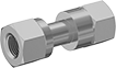
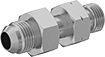
High-Pressure Threaded Fittings for Compressed Gas
Designed to handle high-pressure welding applications, these fittings are commonly used to connect pressure regulators to compressed gas tanks or cylinders. Fittings are also known as CGA (Compressed Gas Association) fittings. They are brass for good corrosion resistance.
Fittings with left-hand threads are identified with a notch in the nut.
Note: Fittings have a CGA number that corresponds to a specific type of gas. Choose a fitting with the same CGA number as your tank and other system components.
![]() For technical drawings and 3-D models, click on a part number.
For technical drawings and 3-D models, click on a part number.
- Maximum Pressure: See table
- Maximum Temperature: 120° F
CGA Number | Tank Connection | Regulator Connection | |||||||||
|---|---|---|---|---|---|---|---|---|---|---|---|
| Tank | Regulator | Thread Size | Thread Type | Thread Direction | Thread Size | Thread Type | Thread Direction | Max. Pressure | For Use With | Each | |
Brass | |||||||||||
| 320 | 580 | 0.830"-14 | NGO | Right Hand | 0.960"-14 | NGO | Right Hand | 3,000 psi @ 72° F | Argon, Carbon Dioxide, Helium, Krypton, Neon, Nitrogen, Xenon | 0000000 | 000000 |
| 346 | 580 | 0.830"-14 | NGO | Right Hand | 0.960"-14 | NGO | Right Hand | 3,000 psi @ 72° F | Air, Argon, Helium, Krypton, Neon, Nitrogen, Xenon | 0000000 | 00000 |
| 350 | 580 | 0.830"-14 | NGO | Left Hand | 0.960"-14 | NGO | Right Hand | 3,000 psi @ 72° F | Argon, Carbon Monoxide, Ethane, Ethylene, Helium, Hydrogen, Krypton, Methane, Methyl Fluoride, Natural Gas, Neon, Nitrogen, Xenon | 0000000 | 00000 |
| 540 | 580 | 0.908"-14 | NGO | Right Hand | 0.960"-14 | NGO | Right Hand | 3,000 psi @ 72° F | Argon, Helium, Krypton, Neon, Nitrogen, Oxygen, Xenon | 0000000 | 00000 |
| 555 | 580 | 0.908"-14 | NGO | Left Hand | 0.960"-14 | NGO | Right Hand | 3,000 psi @ 72° F | Argon, Butane, Helium, Krypton, LP Gas, Neon, Nitrogen, Xenon | 0000000 | 00000 |
- Maximum Pressure: See table
- Maximum Temperature: 120° F
CGA Number | Tank Connection | Regulator Connection | |||||||||
|---|---|---|---|---|---|---|---|---|---|---|---|
| Tank | Regulator | Thread Size | Thread Type | Thread Direction | Thread Size | Thread Type | Thread Direction | Max. Pressure | For Use With | Each | |
Brass | |||||||||||
| 580 | 320 | 0.960"-14 | NGO | Right Hand | 0.830"-14 | NGO | Right Hand | 3,000 psi @ 72° F | Argon, Carbon Dioxide, Helium, Krypton, Neon, Nitrogen, Xenon | 0000000 | 000000 |
| 580 | 346 | 0.960"-14 | NGO | Right Hand | 0.830"-14 | NGO | Right Hand | 3,000 psi @ 72° F | Air, Argon, Helium, Krypton, Neon, Nitrogen, Xenon | 0000000 | 00000 |
| 580 | 350 | 0.960"-14 | NGO | Right Hand | 0.830"-14 | NGO | Left Hand | 3,000 psi @ 72° F | Argon, Carbon Monoxide, Ethane, Ethylene, Helium, Hydrogen, Krypton, Methane, Methyl Fluoride, Natural Gas, Neon, Nitrogen, Xenon | 0000000 | 00000 |
| 580 | 540 | 0.960"-14 | NGO | Right Hand | 0.908"-14 | NGO | Right Hand | 3,000 psi @ 72° F | Argon, Helium, Krypton, Neon, Nitrogen, Oxygen, Xenon | 0000000 | 00000 |
| 580 | 555 | 0.960"-14 | NGO | Right Hand | 0.908"-14 | NGO | Left Hand | 3,000 psi @ 72° F | Argon, Butane, Helium, Krypton, LP Gas, Neon, Nitrogen, Xenon | 0000000 | 00000 |
- Maximum Pressure: 3,000 psi @ 72° F
- Maximum Temperature: 120° F
CGA Number | Tank Connection | Regulator Connection | ||||||||
|---|---|---|---|---|---|---|---|---|---|---|
| Tank | Regulator | Thread Size | Thread Type | Thread Direction | Thread Size | Thread Type | Thread Direction | For Use With | Each | |
Brass | ||||||||||
| 580 | 590 | 0.960"-14 | NGO | Right Hand | 0.960"-14 | NGO | Left Hand | Argon, Helium, Krypton, Neon, Nitrogen, Sulfur Hexafluoride, Xenon | 0000000 | 000000 |
| 590 | 580 | 0.960"-14 | NGO | Left Hand | 0.960"-14 | NGO | Right Hand | Argon, Helium, Krypton, Neon, Nitrogen, Sulfur Hexafluoride, Xenon | 0000000 | 00000 |
Empty High-Pressure Inert Gas Tanks

Safely transport and store inert gas in these tanks.
Outlet | |||||||||||
|---|---|---|---|---|---|---|---|---|---|---|---|
| Tank Style | Capacity, cu. ft. | Dia. | Ht. | Empty Tank Wt., lbs. | Max. Pressure, psi | Material | CGA Number | Gender | Specifications Met | Each | |
For Use With Argon, Argon/Carbon Dioxide Blend, Helium, Nitrogen | |||||||||||
| HP40 | 40 | 7" | 18 1/4" | 22 | 2,015 | Steel | CGA 580 | Female | D.O.T. 3AA-2015 | 0000000 | 0000000 |
| HP55 | 55 | 7" | 23 1/2" | 26.5 | 2,015 | Steel | CGA 580 | Female | D.O.T. 3AA-2015 | 0000000 | 000000 |
| HP80 | 80 | 7" | 31 1/2" | 40 | 2,015 | Steel | CGA 580 | Female | D.O.T. 3AA-2015 | 0000000 | 000000 |
For Use With Argon, Helium, Nitrogen | |||||||||||
| HP20 | 20 | 5 1/4" | 13 3/4" | 10.5 | 2,015 | Steel | CGA 580 | Female | D.O.T. 3AA-2015 | 0000000 | 000000 |
Charging and Gauging Kits for Hydraulic Accumulators


This kit includes the hose, gauge, and fittings needed to charge an accumulator.
Charging and Gauging Kits | Replacement Gas Chucks | ||||||||
|---|---|---|---|---|---|---|---|---|---|
| For Use With | For Accumulator Type | Valve Type | Gender | Pressure Range, psi | Includes | Each | Each | ||
| Nitrogen | Bladder, Diaphragm, Piston | Schrader | Female | 0-3,000 | Charging and Gauging Manifold, Manual Relief Valve, Pressure Gauge, 10-ft. Charging Hose with CGA 580 Fitting, Plastic Carrying Case | 00000000 | 0000000 | 000000000 | 0000000 |