


About Industry Designation for Cable Insulation
More
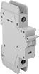
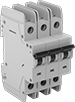
DIN-Rail Mount Equipment Circuit Breakers

Also known as supplemental protectors, these circuit breakers mount directly to DIN rail downstream from a branch circuit breaker to protect a single piece of equipment. They are rated UL1077 for protection against overloads and short circuits. Because they are thermal-magnetic, these breakers trip two ways. They either trip when heat is generated slowly by consistent low-level overload current, or they trip quickly when the magnetic coil senses a high-current short circuit.
Breakthrough current is the maximum current that the circuit breaker can safely stop in the event of a short circuit.
B-trip circuit breakers are best for protecting sensitive equipment, such as programmable logic controllers (PLCs) and sensors, which could be damaged by a spike in current. These circuit breakers will trip if a rush of current reaches 3 to 5 times their rated current.
C-trip circuit breakers are the most common. They’re best for applications such as lighting and control panels, where equipment startup causes a moderate spike in current. They won’t trip until a rush of current reaches 5 to 10 times their rated current.
D-trip circuit breakers prevent nuisance tripping, so they are best for equipment that has a high spike in current at startup, such as transformers, power supplies, and heaters. They will not trip unless a rush of current reaches 10 to 20 times their rated current.
Shunt trips receive a signal from equipment to trip your circuit breaker in situations other than overload or short circuit conditions. For example, use them with a smoke detector to shut off power to a system in the event of a fire.
Auxiliary contacts send a signal to other equipment when the circuit trips. They can activate a warning light, initiate a shutdown, or start a backup power source.
Distribution bars simplify wiring by powering multiple adjacent circuit breakers without needing separate wires for each one. This cuts down on assembly time and space. Cut them to the number of terminals that you need.
Extension terminals raise the wire connection point above distribution bars for easy access to connect power to a set of circuit breakers.
Distribution bar end covers seal the live ends of distribution bars to prevent injury and damage.
Distribution bar terminal covers shield unused, live terminals on distribution bars to prevent injury and damage.
![]() For technical drawings and 3-D models, click on a part number.
For technical drawings and 3-D models, click on a part number.


| Current, A | Voltage | Frequency, Hz | Breakthrough Current | For DIN Rail Size, mm | Wire Connection Type | Ht. | Wd. | Dp. | Temp. Range, °F | Specifications Met | Each | |
B Trip Type | ||||||||||||
|---|---|---|---|---|---|---|---|---|---|---|---|---|
1 Pole—Toggle Style | ||||||||||||
| 10 | 277V AC/48V DC | 50/60 | 10,000 A @ 277 V AC 10,000 A @ 48 V DC | 35 | Screw-Clamp Terminals | 3.15" | 0.7" | 2.36" | -40° to 165° | UL 1077, UL Listed, CSA Certified, CE Marked, IEC 60947-2 | 00000000 | 000000 |
2 Pole—Toggle Style | ||||||||||||
| 10 | 277V AC/480YV AC/96V DC | 50/60 | 10,000 A @ 277 V AC 10,000 A @ 480 V AC 10,000 A @ 96 V DC | 35 | Screw-Clamp Terminals | 3.15" | 1.4" | 2.36" | -40° to 165° | UL 1077, UL Listed, CSA Certified, CE Marked, IEC 60947-2 | 00000000 | 000000 |
3 Pole—Toggle Style | ||||||||||||
| 10 | 277V AC/480YV AC | 50/60 | 10,000 A @ 277 V AC 10,000 A @ 480 V AC | 35 | Screw-Clamp Terminals | 3.15" | 2.09" | 2.36" | -40° to 165° | UL 1077, UL Listed, CSA Certified, CE Marked, IEC 60947-2 | 00000000 | 000000 |
C Trip Type | ||||||||||||
1 Pole—Toggle Style | ||||||||||||
| 10 | 277V AC/48V DC | 50/60 | 10,000 A @ 277 V AC 10,000 A @ 48 V DC | 35 | Screw-Clamp Terminals | 3.15" | 0.7" | 2.36" | -40° to 165° | UL 1077, UL Listed, CSA Certified, CE Marked, IEC 60947-2 | 0000000 | 00000 |
2 Pole—Toggle Style | ||||||||||||
| 10 | 277V AC/480YV AC/96V DC | 50/60 | 10,000 A @ 277 V AC 10,000 A @ 480 V AC 10,000 A @ 96 V DC | 35 | Screw-Clamp Terminals | 3.15" | 1.4" | 2.36" | -40° to 165° | UL 1077, UL Listed, CSA Certified, CE Marked, IEC 60947-2 | 0000000 | 00000 |
3 Pole—Toggle Style | ||||||||||||
| 10 | 277V AC/480YV AC | 50/60 | 10,000 A @ 277 V AC 10,000 A @ 480 V AC | 35 | Screw-Clamp Terminals | 3.15" | 2.09" | 2.36" | -40° to 165° | UL 1077, UL Listed, CSA Certified, CE Marked, IEC 60947-2 | 0000000 | 000000 |
D Trip Type | ||||||||||||
1 Pole—Toggle Style | ||||||||||||
| 10 | 277V AC/48V DC | 50/60 | 5,000 A @ 277 V AC 5,000 A @ 48 V DC | 35 | Screw-Clamp Terminals | 3.15" | 0.7" | 2.36" | -40° to 165° | UL 1077, UL Listed, CSA Certified, CE Marked, IEC 60947-2 | 00000000 | 00000 |
2 Pole—Toggle Style | ||||||||||||
| 10 | 277V AC/480YV AC/96V DC | 50/60 | 5,000 A @ 277 V AC 5,000 A @ 480 V AC 5,000 A @ 96 V DC | 35 | Screw-Clamp Terminals | 3.15" | 1.4" | 2.36" | -40° to 165° | UL 1077, UL Listed, CSA Certified, CE Marked, IEC 60947-2 | 00000000 | 00000 |
3 Pole—Toggle Style | ||||||||||||
| 10 | 277V AC/480YV AC | 50/60 | 5,000 A @ 277 V AC 5,000 A @ 480 V AC | 35 | Screw-Clamp Terminals | 3.15" | 2.09" | 2.36" | -40° to 165° | UL 1077, UL Listed, CSA Certified, CE Marked, IEC 60947-2 | 00000000 | 000000 |
| Voltage | Current, A | Frequency, Hz | For DIN Rail Size, mm | Wire Connection Type | Ht. | Wd. | Dp. | Temp. Range, °F | Specifications Met | Each | |
| 12-110V AC/12-60V DC | 63 | 50/60 | 35 | Screw-Clamp Terminals | 4.13" | 0.7" | 2.36" | 25° to 100° | UL 489, UL Listed, CSA Certified, CE Marked, IEC 60898 | 00000000 | 000000 |
| 110-415V AC/110-230V DC | 40 | 50/60 | 35 | Screw-Clamp Terminals | 4.13" | 0.7" | 2.36" | 25° to 100° | UL 489, UL Listed, CSA Certified, CE Marked, IEC 60898 | 00000000 | 00000 |

| Voltage | Current, A | Frequency, Hz | Industry Designation | No. of Circuits Controlled | Switch Starting Position | For DIN Rail Size, mm | Wire Connection Type | Ht. | Wd. | Dp. | Temp. Range, °F | Specifications Met | Each | |
| 230V AC | 6 | 50/60 | DPST | 2 | 1 Off (Normally Open) and 1 On (Normally Closed) | 35 | Screw-Clamp Terminals | 3.15" | 0.35" | 2.36" | -40° to 165° F | UL 1077, UL Listed, CSA Certified, CE Marked, IEC 60947-2 | 00000000 | 000000 |

Terminal | ||||||||||||
|---|---|---|---|---|---|---|---|---|---|---|---|---|
| For No. of Poles | No. of Terminals | Voltage | Current, A | Ctr.-to-Ctr. | Wd. | Ht. | Wd. | Dp. | Temp. Range, °F | Specifications Met | Each | |
| 1 | 57 | 277V AC/480YV AC | 80 | 0.7" | 0.22" | 0.59" | 39.72" | 0.59" | 25° to 212° | UL 1077, UL Listed, CE Marked, IEC 60947-2 | 00000000 | 000000 |
| 2 | 56 | 277V AC/480YV AC | 80 | 0.7" | 0.24" | 1.46" | 39.02" | 0.87" | 25° to 212° | UL 1077, UL Listed, CE Marked, IEC 60947-2 | 00000000 | 000000 |
| 3 | 57 | 277V AC/480YV AC | 80 | 0.7" | 0.24" | 1.46" | 39.72" | 0.87" | 25° to 212° | UL 1077, UL Listed, CE Marked, IEC 60947-2 | 00000000 | 000000 |

| For No. of Poles | Voltage | Current, A | Frequency, Hz | Wire Connection Type | Ht. | Wd. | Dp. | Temp. Range, °F | Specifications Met | Each | |
| 1 | 277V AC/480YV AC | 115 | 50/60 | Screw-Clamp Terminals | 1.14" | 1.42" | 0.67" | -40° to 165° | UL 1077, UL Listed, CSA Certified, CE Marked, IEC 60947-2 | 00000000 | 000000 |
| 2, 3 | 277V AC/480YV AC | 4 | 50/60 | Screw-Clamp Terminals | 1.14" | 2.36" | 0.67" | -40° to 165° | UL 1077, UL Listed, CSA Certified, CE Marked, IEC 60947-2 | 00000000 | 00000 |


| For No. of Terminals | Ht. | Wd. | Dp. | Material | Temp. Range, °F | Specifications Met | Each | |
| 5 | 0.94" | 3.35" | 0.47" | Plastic | -40° to 165° | UL 1077, CSA Certified, CE Marked, IEC 60947-2 | 00000000 | 00000 |
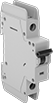
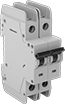
DIN-Rail Mount Branch Circuit Breakers
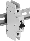
Mount these circuit breakers directly to DIN rail to protect equipment and wiring in an area of your facility from overloads and short circuits. They meet UL 489 requirements for branch circuit protection and are certified as current limiting, so they protect equipment by minimizing passing current during a short circuit. Because they are thermal-magnetic, these breakers trip two ways. They either trip when heat is generated slowly by consistent low-level overload current, or they trip quickly when the magnetic coil senses a high-current short circuit.
Breakthrough current is the maximum current that the circuit breaker can safely stop in the event of a short circuit.
B-trip circuit breakers are best for protecting sensitive equipment, such as programmable logic controllers (PLCs) and sensors, which could be damaged by a spike in current. These circuit breakers will trip if a rush of current reaches 3 to 5 times their rated current.
C-trip circuit breakers are the most common. They’re best for applications such as lighting and control panels, where equipment startup causes a moderate spike in current. They won’t trip until a rush of current reaches 5 to 10 times their rated current.
D-trip circuit breakers prevent nuisance tripping, so they are best for equipment that has a high spike in current at startup, such as transformers, power supplies, and heaters. They will not trip unless a rush of current reaches 10 to 20 times their rated current.
Shunt trips receive a signal from equipment to trip your circuit breaker in situations other than overload or short circuit conditions. For example, use them with a smoke detector to shut off power to a system in the event of a fire.
Auxiliary contacts send a signal to other equipment when the circuit trips. They can activate a warning light, initiate a shutdown, or start a backup power source.
Distribution bars simplify wiring by powering multiple adjacent circuit breakers without needing separate wires for each one. This cuts down on assembly time and space.
Extension terminals raise the wire connection point above distribution bars for easy access to connect power to a set of circuit breakers.
Distribution bar terminal covers shield unused, live terminals on distribution bars to prevent injury and damage.
![]() For technical drawings and 3-D models, click on a part number.
For technical drawings and 3-D models, click on a part number.
| Current, A | Voltage | Frequency, Hz | Breakthrough Current | For DIN Rail Size, mm | Wire Connection Type | Ht. | Wd. | Dp. | Temp. Range, °F | Specifications Met | Each | |
B Trip Type | ||||||||||||
|---|---|---|---|---|---|---|---|---|---|---|---|---|
1 Pole—Toggle Style | ||||||||||||
| 10 | 277V AC/48V DC | 50/60 | __ | 35 | Screw-Clamp Terminals | 4.13" | 0.7" | 2.36" | -10° to 165° | UL 489, CSA Certified, CE Marked, IEC 60947-2 | 00000000 | 000000 |
2 Pole—Toggle Style | ||||||||||||
| 10 | 277V AC/480YV AC/96V DC | 50/60 | __ | 35 | Screw-Clamp Terminals | 4.13" | 1.4" | 2.36" | -10° to 165° | UL 489, CSA Certified, CE Marked, IEC 60947-2 | 00000000 | 00000 |
3 Pole—Toggle Style | ||||||||||||
| 10 | 277V AC/480YV AC | 50/60 | __ | 35 | Screw-Clamp Terminals | 4.13" | 2.09" | 2.36" | -10° to 165° | UL 489, CSA Certified, CE Marked, IEC 60947-2 | 00000000 | 000000 |
C Trip Type | ||||||||||||
1 Pole—Toggle Style | ||||||||||||
| 10 | 277V AC/48V DC | 50/60 | 10,000 A @ 277 V AC 10,000 A @ 48 V DC | 35 | Screw-Clamp Terminals | 4.13" | 0.7" | 2.36" | -10° to 165° | UL 489, CSA Certified, CE Marked, IEC 60947-2 | 0000000 | 00000 |
2 Pole—Toggle Style | ||||||||||||
| 10 | 125V DC/250V DC | 50/60 | 10,000 A @ 125 V DC 10,000 A @ 250 V DC | 35 | Screw-Clamp Terminals | 4.13" | 1.4" | 2.36" | -10° to 165° | UL 489, CSA Certified, CE Marked, IEC 60947-2 | 00000000 | 000000 |
| 10 | 277V AC/480YV AC/96V DC | 50/60 | 10,000 A @ 277 V AC 10,000 A @ 480 V AC 10,000 A @ 96 V DC | 35 | Screw-Clamp Terminals | 4.13" | 1.4" | 2.36" | -10° to 165° | UL 489, CSA Certified, CE Marked, IEC 60947-2 | 0000000 | 000000 |
3 Pole—Toggle Style | ||||||||||||
| 10 | 277V AC/480YV AC | 50/60 | 10,000 A @ 277 V AC 10,000 A @ 480 V AC | 35 | Screw-Clamp Terminals | 4.13" | 2.09" | 2.36" | -10° to 165° | UL 489, CSA Certified, CE Marked, IEC 60947-2 | 0000000 | 000000 |
D Trip Type | ||||||||||||
1 Pole—Toggle Style | ||||||||||||
| 10 | 277V AC/48V DC | 50/60 | 10,000 A @ 277 V AC 10,000 A @ 48 V DC | 35 | Screw-Clamp Terminals | 4.13" | 0.7" | 2.36" | -10° to 165° | UL 489, CSA Certified, CE Marked, IEC 60947-2 | 00000000 | 00000 |
2 Pole—Toggle Style | ||||||||||||
| 10 | 277V AC/480YV AC/96V DC | 50/60 | 10,000 A @ 277 V AC 10,000 A @ 480 V AC 10,000 A @ 96 V DC | 35 | Screw-Clamp Terminals | 4.13" | 1.4" | 2.36" | -10° to 165° | UL 489, CSA Certified, CE Marked, IEC 60947-2 | 00000000 | 000000 |
3 Pole—Toggle Style | ||||||||||||
| 10 | 277V AC/480YV AC | 50/60 | 10,000 A @ 277 V AC 10,000 A @ 480 V AC | 35 | Screw-Clamp Terminals | 4.13" | 2.09" | 2.36" | -10° to 165° | UL 489, CSA Certified, CE Marked, IEC 60947-2 | 00000000 | 000000 |
| Voltage | Current, A | Frequency, Hz | For DIN Rail Size, mm | Wire Connection Type | Ht. | Wd. | Dp. | Temp. Range, °F | Specifications Met | Each | |
| 12-110V AC/12-60V DC | 63 | 50/60 | 35 | Screw-Clamp Terminals | 4.13" | 0.7" | 2.36" | 25° to 100° | UL 489, UL Listed, CSA Certified, CE Marked, IEC 60898 | 00000000 | 000000 |
| 110-415V AC/110-230V DC | 40 | 50/60 | 35 | Screw-Clamp Terminals | 4.13" | 0.7" | 2.36" | 25° to 100° | UL 489, UL Listed, CSA Certified, CE Marked, IEC 60898 | 00000000 | 00000 |

| Voltage | Current, A | Frequency, Hz | Industry Designation | No. of Circuits Controlled | Switch Starting Position | For DIN Rail Size, mm | Wire Connection Type | Ht. | Wd. | Dp. | Temp. Range, °F | Specifications Met | Each | |
| 250V AC | 6 | 50/60 | DPST | 2 | 1 Off (Normally Open) and 1 On (Normally Closed) | 35 | Screw-Clamp Terminals | 3.78" | 0.35" | 2.36" | -10° to 165° F | UL 489, UL Listed, CSA Certified, CE Marked, IEC 60898 | 00000000 | 000000 |

Terminal | |||||||||||||
|---|---|---|---|---|---|---|---|---|---|---|---|---|---|
| For No. of Poles | No. of Terminals | Voltage | Current, A | Frequency, Hz | Ctr.-to-Ctr. | Wd. | Ht. | Wd. | Dp. | Temp. Range, °F | Specifications Met | Each | |
| 1 | 12 | 277V AC/480YV AC/96V DC | 80 | 50/60 | 0.7" | 0.2" | 1.28" | 8.06" | 0.61" | -10° to 165° | UL 489, UL Recognized Component, CE Marked, IEC 60898 | 00000000 | 000000 |
| 2 | 12 | 277V AC/480YV AC/96V DC | 80 | 50/60 | 0.7" | 0.2" | 1.28" | 8.06" | 0.61" | -10° to 165° | UL 489, UL Recognized Component, CE Marked, IEC 60898 | 00000000 | 00000 |
| 3 | 12 | 277V AC/480YV AC/96V DC | 80 | 50/60 | 0.7" | 0.2" | 1.28" | 8.06" | 0.61" | -10° to 165° | UL 489, UL Recognized Component, CE Marked, IEC 60898 | 00000000 | 00000 |
| For No. of Poles | Voltage | Current, A | Frequency, Hz | Wire Connection Type | Ht. | Wd. | Dp. | Temp. Range, °F | Specifications Met | Each | |
| 1, 2, 3 | 480V AC/96V DC | 80 | 50/60 | Screw-Clamp Terminals | 2.82" | 0.64" | 1.23" | -10° to 165° | UL 489, UL Recognized Component, CE Marked, IEC 60898 | 0000000 | 000000 |

| For No. of Terminals | Ht. | Wd. | Dp. | Material | Temp. Range, °F | Specifications Met | Each | |
| 3 | 0.94" | 1.9" | 0.63" | Plastic | -10° to 165° | UL 489, UL Recognized Component, CE Marked, IEC 60898 | 00000000 | 00000 |
DIN-Rail Mount Electronic Circuit Breakers
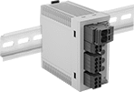
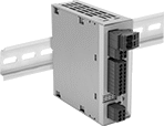
An electronic trip mechanism makes these circuit breakers fast, precise, and consistent. They continuously monitor current and trip at a precise value compared to the much wider current range in traditional thermal-magnetic breakers. They're good for protecting devices that could be easily damaged by overcurrent such as sensors, HMIs, and controllers. Because they trip electronically, they don't require the bulky housing necessary for thermal trip mechanisms, so they take up less space in your control cabinet. They also eliminate the need for accessories, such as shunt trips, because they can be remotely monitored and controlled. For at the source troubleshooting, they have an indicator light and on/off/reset button for each circuit. To make sure your equipment is receiving the correct voltage, these breakers will also trip when the supply voltage goes under or over a set value.
Adjustable-current breakers let you choose the current at which they’ll trip. As your operation changes, you can adjust when these breakers will trip rather than replacing the entire breaker. Breakers that control 4 or 8 circuits allow you to individually set each circuit. If one trips, the others will keep working.
Breakers with digital input/outputs send and receive signals, so you can remotely check the status of your breaker, reset it, and turn it on and off. Breakers with IO Link give you more control than breakers with digital input/outputs. Not only can you check the status to reset or turn your breaker on and off, but you can also adjust their current and view current in real-time. This is helpful when troubleshooting issues such as a breaker that repeatedly trips.
![]() For technical drawings and 3-D models, click on a part number.
For technical drawings and 3-D models, click on a part number.
| No. of Circuits Controlled | Current, A | Voltage | No. of Inputs | No. of Outputs | For DIN Rail Size, mm | Wire Connection Type | Ht. | Wd. | Dp. | Temp. Range, °F | Environmental Rating | Each | |
Push Button Style | |||||||||||||
|---|---|---|---|---|---|---|---|---|---|---|---|---|---|
| 4 | 2, 3, 4, 5, 6, 7, 8, 9, 10 | 24V DC | 1 | 2 | 35 | Spring-Clamp Terminals | 3.54" | 1.77" | 4.55" | -10° to 145° | IP20 | 0000000 | 0000000 |
| 8 | 2, 3, 4, 5, 6, 7, 8, 9, 10 | 24V DC | 1 | 2 | 35 | Spring-Clamp Terminals | 5" | 1.65" | 5.61" | -10° to 145° | IP20 | 0000000 | 000000 |
| No. of Circuits Controlled | Current, A | Voltage | For DIN Rail Size, mm | Wire Connection Type | Ht. | Wd. | Dp. | Temp. Range, °F | Environmental Rating | Each | |
Push Button Style | |||||||||||
|---|---|---|---|---|---|---|---|---|---|---|---|
| 4 | 1, 2, 3, 4, 5, 6, 7, 8, 9, 10 | 24V DC | 35 | Spring-Clamp Terminals | 3.54" | 1.77" | 4.55" | -10° to 145° | IP20 | 0000000 | 0000000 |
| 8 | 1, 2, 3, 4, 5, 6, 7, 8, 9, 10 | 24V DC | 35 | Spring-Clamp Terminals | 5" | 1.65" | 5.61" | -10° to 145° | IP20 | 0000000 | 000000 |
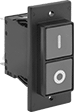
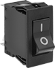
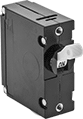
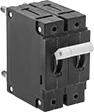
Panel-Mount Equipment Circuit Breakers
Mount these breakers, also known as supplemental protectors, through panels downstream from a branch circuit breaker to protect a single piece of equipment. They are rated UL1077 for protection against overloads and short circuits. These breakers can also be used as on/off switches. All are thermal, so they use the heat generated in overcurrent situations to trip the breaker.
Breakthrough current is the maximum current that the circuit breaker can safely stop in the event of a short circuit.
Covers for rocker style breakers (sold separately) provide IP54 protection against limited dust and splashed water.
Covers for push-button style breakers (sold separately) provide IP65 protection against water projected from a nozzle.
![]() For technical drawings and 3-D models, click on a part number.
For technical drawings and 3-D models, click on a part number.
For Panel Cutout | Mounting Holes | |||||||||||||
|---|---|---|---|---|---|---|---|---|---|---|---|---|---|---|
| Current, A | Voltage | Frequency, Hz | Breakthrough Current | Ht. | Wd. | Dp. Behind Panel | No. of | Dia. | Mounting Fasteners Included | Quick-Disconnect Tab Wd. | Temp. Range, °F | Specifications Met | Each | |
1 Pole | ||||||||||||||
| 10 | 240V AC/60V DC | 50/60 | 1,000 A @ 240 V AC 1,000 A @ 60 V DC | 1.98" | 0.99" | 1.96" | 2 | 0.15" | No | 0.25" | 15° to 130° | UL 1077, UL Recognized Component, CSA Certified | 0000000 | 000000 |
2 Pole | ||||||||||||||
| 10 | 240V AC/60V DC | 50/60 | 1,000 A @ 240 V AC 1,000 A @ 60 V DC | 1.98" | 0.99" | 1.96" | 2 | 0.15" | No | 0.25" | 15° to 130° | UL 1077, UL Recognized Component, CSA Certified | 0000000 | 00000 |
For Panel Cutout | |||||||||||
|---|---|---|---|---|---|---|---|---|---|---|---|
| Current, A | Voltage | Frequency, Hz | Breakthrough Current | Ht. | Wd. | Dp. Behind Panel | Quick-Disconnect Tab Wd. | Temp. Range, °F | Specifications Met | Each | |
1 Pole | |||||||||||
| 10 | 240V AC/60V DC | 50/60 | 1,000 A @ 240 V AC 1,000 A @ 60 V DC | 1.77" | 0.85" | 1.75" | 0.25" | 15° to 130° | UL 1077, UL Recognized Component, CSA Certified | 0000000 | 000000 |
2 Pole | |||||||||||
| 10 | 240V AC/60V DC | 50/60 | 1,000 A @ 240 V AC 1,000 A @ 60 V DC | 1.77" | 0.85" | 1.75" | 0.25" | 15° to 130° | UL 1077, UL Recognized Component, CSA Certified | 0000000 | 00000 |
| Current, A | Voltage | Frequency, Hz | Breakthrough Current | For Panel Cutout Dia. | Dp. Behind Panel | Mounting Fasteners Included | Quick-Disconnect Tab Wd. | Temp. Range, °F | Specifications Met | Each | |
1 Pole | |||||||||||
|---|---|---|---|---|---|---|---|---|---|---|---|
| 10 | 250V AC/75V DC | 50/60 | 2,000 A @ 250 V AC 800 A @ 75 V DC | 1/4" | 2.42" | Yes | 0.25" | -20° to 140° | UL 1077, UL Recognized Component | 0000000 | 000000 |
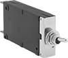
High-Temperature Panel-Mount Circuit Breakers
Unlike breakers that trip thermally, these breakers have a hydraulic-magnetic trip mechanism, so they aren’t affected by changes in temperature. Instead, these circuit breakers trip when they hydraulically sense consistent low-level overload current, or they trip quickly when the magnetic coil senses a high-current short circuit. Use the threaded holes on the face to install them through panels, enclosure covers, or walls to keep them close to the equipment they protect.
Breakthrough current is the maximum current that the circuit breaker can safely stop in the event of a short circuit.
![]() For technical drawings and 3-D models, click on a part number.
For technical drawings and 3-D models, click on a part number.
For Panel Cutout | Mounting Holes | |||||||||||||
|---|---|---|---|---|---|---|---|---|---|---|---|---|---|---|
| Current, A | Voltage | Frequency, Hz | Breakthrough Current | Temp. Range, °F | Dia. | Dp. Behind Panel | No. of | Thread Size | Mounting Fasteners Included | Wire Connection Type | Ht. | Wd. | Each | |
1 Pole—Toggle Style | ||||||||||||||
| 10 | 277V AC/80V DC | 50/60 | 5,000 A @ 277 V AC 7,500 A @ 80 V DC | -40° to 185° | 0.63" | 2" | 2 | 6-32 | No | Quick-Disconnect Terminals | 2" | 0.75" | 000000000 | 000000 |
2 Pole—Toggle Style | ||||||||||||||
| 10 | 277V AC/80V DC | 50/60 | 5,000 A @ 277 V AC 7,500 A @ 80 V DC | -40° to 185° | 0.63" | 2" | 4 | 6-32 | No | Quick-Disconnect Terminals | 2" | 1.5" | 00000000 | 00000 |
Blade-Style Circuit Breakers
Protect against overload and short circuits in low-voltage automotive and other electronic applications. These circuit breakers can replace type ATC, AF, ATO, and 257 blade-style fuses. They are thermal, so they trip when heat is generated by overload current.
Breakthrough current is the maximum current that the circuit breaker can safely stop in the event of a short circuit.
Automatic reset breakers don’t require you to manually reset them after they trip, so they’re good for areas where the breaker isn’t easily accessed. These breakers reset once they cool. However, they will trip repeatedly if the overcurrent condition continues.
Manual reset breakers require you to push a button after they trip.
Place UL1077 rated breakers downstream from a branch circuit breaker to protect a single piece of equipment from overloads and short circuits. They are also known as supplemental protectors.
![]() For technical drawings and 3-D models, click on a part number.
For technical drawings and 3-D models, click on a part number.
| Current, A | Breakthrough Current | Mounting Location | Ht. | Wd. | Blade Ht. | Temp. Range, °F | Environmental Rating | Specifications Met | Each | |
12V DC | ||||||||||
|---|---|---|---|---|---|---|---|---|---|---|
| 10 | 2,000 A @ 12 V DC | Fuse Block | 0.95" | 0.79" | 0.25" | -40° to 185° | IP54 | SAE J553 | 0000000 | 00000 |
| Current, A | Breakthrough Current | Mounting Location | Ht. | Wd. | Blade Ht. | Temp. Range, °F | Environmental Rating | Specifications Met | Each | |
24V DC | ||||||||||
|---|---|---|---|---|---|---|---|---|---|---|
| 10 | 2,000 A @ 24 V DC | Fuse Block | 1.16" | 0.79" | 0.25" | -40° to 185° | IP30 | __ | 0000000 | 000000 |
48V DC | ||||||||||
| 10 | 2,000 A @ 48 V DC | Fuse Block | 1 1/2" | 0.87" | 0.25" | -40° to 185° | IP40 | SAE J553 | 0000000 | 00000 |
250V AC/72V DC | ||||||||||
| 10 | 2,000 A @ 250 V AC 2,000 A @ 72 V DC | Fuse Block | 2.06" | 0.96" | 0.25" | 0° to 140° | __ | UL 1077, UL Recognized Component, CSA Certified | 0000000 | 00000 |

| For DIN Rail Size, mm | Wire Connection Type | Each | |
| 35 | Screw-Clamp Terminals | 000000 | 000000 |
Plug-Base Circuit Breakers

Replace any Edison-base fuse with these resettable circuit breakers. They are thermal, so they trip when heat is generated by overload current.
Breakthrough current is the maximum current that the circuit breaker can safely stop in the event of a short circuit.
![]() For technical drawings and 3-D models, click on a part number.
For technical drawings and 3-D models, click on a part number.
| Current, A | Voltage | Manufacturer Fuse Equivalent | Circuit Breaker Type | Breakthrough Current | Mounting Location | Specifications Met | Each | |
Push Button Style | ||||||||
|---|---|---|---|---|---|---|---|---|
| 10 | 120V AC | T, TL, W | Thermal | 5,000 A @ 120 V AC | Fuse Panel | UL Listed | 000000 | 000000 |
Electronic Equipment Outlet Strips

Power computers, lab equipment, and office machines that have IEC connections. These outlet strips have a circuit breaker to prevent damage from current overload and short circuits. Connect an IEC C13 power cord (not included) to the plug on the end to power these outlet strips.
![]() For technical drawings and 3-D models, click on a part number.
For technical drawings and 3-D models, click on a part number.
Mounting Holes | |||||||||||||
|---|---|---|---|---|---|---|---|---|---|---|---|---|---|
| No. of Outlets | Outlet Ctr.-to-Ctr. | Current, A | Voltage | Features | Material | Protection Type | Mounting Fasteners Included | No. of | Dia | Specifications Met | Color | Each | |
IEC C13 Socket with IEC C14 Plug | |||||||||||||
| 4 | 7/8" | 10 | 250V AC | IEC C14 Inlet Connector, Power Switch | ABS Plastic | Circuit Breaker | No | 1 | 0.24" | UL Listed | Black | 0000000 | 000000 |
Automatic-Wind Cord Reels
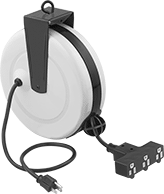
A ratchet holds the extension cord on these reels in place at any length; a quick pull releases the cord and the spring-driven winding mechanism retracts it. An adjustable ball lock controls how much cord retracts into the reel.
Reels with a swivel eye hook mount to the ceiling, so you can keep your cord on hand but out of the way.
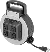
Reels with a carrying handle can be taken where you need them. Their extension cord acts as a power cord.
Reels with a circuit breaker trip if there’s too much current to prevent overload damage.
Extension Cord | Power Cord | ||||||||||||||||
|---|---|---|---|---|---|---|---|---|---|---|---|---|---|---|---|---|---|
| No. of Outlets | Lg., ft. | Wire Ga. | Industry Designation | Lg. | Wire Ga. | Housing Material | Current, A | Voltage | Protection Type | Lg. | Wd. | Ht. | Features | Specifications Met | Color | Each | |
Extension Cord with NEMA 5-15 Socket and Power Cord with NEMA 5-15 Plug | |||||||||||||||||
| 3 | 30 | 16 | SJT | 18" | 16 | Steel | 10 | 120V AC | Circuit Breaker | 9 1/2" | 3" | 11 1/4" | Adjustable Ball Lock, Ratchet, Swivel Eye Hook | UL Listed | Yellow | 0000000 | 000000 |
NEMA 5-15 Outlet and Extension Cord with NEMA 5-15 Plug | |||||||||||||||||
| 4 | 25 | 16 | SJT | __ | __ | Steel | 10 | 125V AC | Circuit Breaker | 8 1/8" | 4 3/4" | 10 7/8" | Adjustable Ball Lock, Carrying Handle, Power-Indicating Light, Ratchet | ETL Listed, C-ETL Listed | Blue | 0000000 | 000000 |
Impact-Resistant Automatic-Wind Cord Reels
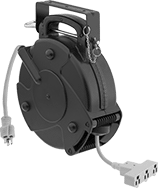 With Three Outlets | NEMA 5-15 Plug |
NEMA 5-15 Socket |
Made of impact-resistant plastic, these reels are more durable than other automatic-wind cord reels. They have a ratchet to hold the extension cord in place at any length; a quick pull releases the cord and the spring-driven winding mechanism retracts it. A resettable circuit breaker prevents overload damage. Mount reels to a wall or ceiling with the quick-release mounting bracket. The included extension cord resists oil and water.
Extension Cord | Power Cord | ||||||||||||||||
|---|---|---|---|---|---|---|---|---|---|---|---|---|---|---|---|---|---|
| No. of Outlets | Lg., ft. | Wire Ga. | Industry Designation | Lg., ft. | Wire Ga. | Housing Material | Current, A | Voltage | Protection Type | Lg. | Wd. | Ht. | Features | Specifications Met | Color | Each | |
Extension Cord with NEMA 5-15 Socket and Power Cord with NEMA 5-15 Plug | |||||||||||||||||
| 3 | 75 | 14 | SJTOW | 3 | 14 | Plastic | 10 | 120V AC | Circuit Breaker | 13 1/2" | 5 1/2" | 15 1/2" | Carrying Handle, Lockable Outlet, Quick-Release Mounting Bracket, Ratchet | ETL Listed, C-ETL Listed | Black | 0000000 | 0000000 |