


Corner Machine Brackets


Made to meet tight dimensional tolerances for mounting applications on machines and automated equipment.
![]() For technical drawings and 3-D models, click on a part number.
For technical drawings and 3-D models, click on a part number.
Lg. | Mounting | Each | |||||||||||||
|---|---|---|---|---|---|---|---|---|---|---|---|---|---|---|---|
| (A) | (B) | (C) | Lg. Tolerance | Thick. | Thick. Tolerance | Angle | Angle Tolerance | Corner Radius | Flatness Tolerance | Fasteners Included | Number of Slots | For Screw Size | 1-19 | 20-Up | |
Metric | |||||||||||||||
6061 Aluminum | |||||||||||||||
| 35mm | 30mm | 30mm | -0.5mm to 0.5mm | 3mm | -0.2mm to 0.2mm | 90° | -1° to 1° | 3.2mm | -0.38mm to 0.38mm | No | 2 | M6 | 0000000 | 00000 | 00000 |
| 80mm | 40mm | 50mm | -0.5mm to 0.5mm | 3mm | -0.2mm to 0.2mm | 90° | -1° to 1° | 3.2mm | -0.38mm to 0.38mm | No | 4 | M6 | 0000000 | 00000 | 00000 |
316 Stainless Steel | |||||||||||||||
| 35mm | 30mm | 30mm | -0.5mm to 0.5mm | 3mm | -0.2mm to 0.2mm | 90° | -1° to 1° | 3.2mm | -0.38mm to 0.38mm | No | 2 | M6 | 0000000 | 0000 | 0000 |
| 80mm | 40mm | 60mm | -0.5mm to 0.5mm | 3mm | -0.2mm to 0.2mm | 90° | -1° to 1° | 3.2mm | -0.38mm to 0.38mm | No | 4 | M6 | 0000000 | 00000 | 00000 |
Flat-Surface Machine Brackets

Used for mounting applications on machines and automated equipment, these brackets are made to meet tight dimensional tolerances.
![]() For technical drawings and 3-D models, click on a part number.
For technical drawings and 3-D models, click on a part number.
Lg. | Mounting | |||||||||
|---|---|---|---|---|---|---|---|---|---|---|
| (A) | (C) | Lg. Tolerance | Thick. | Thick. Tolerance | Flatness Tolerance | Fasteners Included | Number of Slots | For Screw Size | Each | |
Metric | ||||||||||
6061 Aluminum | ||||||||||
| 60mm | 20mm | -0.5mm to 0.5mm | 3mm | -0.2mm to 0.2mm | -0.38mm to 0.38mm | No | 2 | M6 | 0000000 | 00000 |
316 Stainless Steel | ||||||||||
| 60mm | 20mm | -0.5mm to 0.5mm | 3mm | -0.2mm to 0.2mm | -0.38mm to 0.38mm | No | 2 | M6 | 0000000 | 0000 |
Offset-Surface Machine Brackets

With tight dimensional tolerances, these brackets are good for mounting applications on machines and automated equipment.
![]() For technical drawings and 3-D models, click on a part number.
For technical drawings and 3-D models, click on a part number.
Lg. | Mounting | ||||||||||||||
|---|---|---|---|---|---|---|---|---|---|---|---|---|---|---|---|
| (A) | (B) | (C) | Offset | Lg. Tolerance | Thick. | Thick. Tolerance | Angle | Angle Tolerance | Corner Radius | Flatness Tolerance | Fasteners Included | Number of Slots | For Screw Size | Each | |
Metric | |||||||||||||||
316 Stainless Steel | |||||||||||||||
| 40mm | 45mm | 45mm | 25mm | -0.5mm to 0.5mm | 3mm | -0.2mm to 0.2mm | 90° | -1° to 1° | 3.2mm | -0.38mm to 0.38mm | No | 4 | M6 | 0000000 | 000000 |
Sensor and Switch Mounting Brackets


Position proximity, photoelectric, and light beam sensors and switches.
![]() For technical drawings and 3-D models, click on a part number.
For technical drawings and 3-D models, click on a part number.
Lg., mm | Mounting | ||||||||||
|---|---|---|---|---|---|---|---|---|---|---|---|
| Style | For Sensor/Switch OD, mm | Material | (A) | (B) | (C) | Thick., mm | Fasteners Included | Number of Holes | For Screw Size | Each | |
| 5 | 18 | 304 Stainless Steel | 38 | 25 | 39 | 3 | No | 2 | M6 | 000000000 | 000000 |
| 5 | 22 | 304 Stainless Steel | 38 | 25 | 39 | 3 | No | 2 | M6 | 000000000 | 00000 |
| 5 | 24 | 304 Stainless Steel | 38 | 25 | 39 | 3 | No | 2 | M6 | 000000000 | 00000 |
| 6 | 18 | 304 Stainless Steel | 38 | __ | 58 | 3.1 | No | 2 | M6 | 000000000 | 00000 |
| 6 | 22 | 304 Stainless Steel | 38 | __ | 58 | 3.1 | No | 2 | M6 | 000000000 | 00000 |
| 6 | 24 | 304 Stainless Steel | 38 | __ | 58 | 3.1 | No | 2 | M6 | 000000000 | 00000 |
Lg., mm | Sensor/Switch Mounting | Surface Mounting | |||||||||||||
|---|---|---|---|---|---|---|---|---|---|---|---|---|---|---|---|
| Style | Material | (A) | (B) | (C) | Thick., mm | Fasteners Included | Number of Slots | Number of Holes | For Screw Size | Fasteners Included | Number of Slots | Number of Holes | For Screw Size | Each | |
| 11 | Zinc-Plated Iron | 50 | 22 | 60 | 2 | Yes | 2 | 2 | M4 | Yes | 2 | 1 | M6 | 000000000 | 00000 |
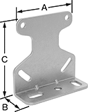
Standoff Brackets


Combine with a U-bolt or routing clamp to convey a variety of material, such as pipe, tubing, and cable raceway, at distance from floors, walls, and ceilings. The extra clearance allows access for maintenance and adding and removing lines.
![]() For technical drawings and 3-D models, click on a part number.
For technical drawings and 3-D models, click on a part number.
Mounting Hole (A) | Mounting Hole (B) | ||||||||||||||
|---|---|---|---|---|---|---|---|---|---|---|---|---|---|---|---|
| Lg. | Wd. | Ht. | Thick. | Wd. | Lg. | Ctr.-to-Ctr. | Wd. | Lg. | Ctr.-to-Ctr. | No. of Mounting Holes | For Screw Size | Mounting Fasteners Included | Cap., lbs. | Each | |
Galvanized Steel | |||||||||||||||
| 6 5/16" | 1 3/16" | 1 15/16" | 1/8" | 5/16" | 9/16" | 5 1/8" | 1/4" | 3" | __ | 3 | 1/4", M6 | No | 110 | 0000000 | 000000 |
| 8 1/4" | 1 3/16" | 1 15/16" | 1/8" | 5/16" | 9/16" | 7 1/16" | 1/4" | 2" | 3 1/8" | 4 | 1/4", M6 | No | 110 | 0000000 | 00000 |
| 10 1/4" | 1 3/16" | 1 15/16" | 1/8" | 5/16" | 9/16" | 9 1/16" | 1/4" | 2 15/16" | 3 15/16" | 4 | 1/4", M6 | No | 110 | 0000000 | 00000 |