


About Pipe Size
More
About Pressure Gauges
More
Steam Pressure Gauges
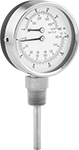
Designed for use with boilers, these gauges have a dual scale that displays pressure in psi and feet of H₂O and displays temperature in °F/°C.
- For Use With: Steam and Water
- Accuracy: ±2.5% Full Scale (Grade B)
Available Pressure Ranges | |||||
|---|---|---|---|---|---|
Pressure Range | Graduation Marks | Numeric Increments | |||
| psi | ft. of H₂O | psi | ft. of H₂O | psi | ft. of H₂O |
2 1/2" Dial Dia. | |||||
| 0 to 75 | 0 to 170 | 5 | 10 | 20 | 50 |
3 1/4" Dial Dia. | |||||
| 0 to 100 | 0 to 230 | 2 | 10 | 20 | 50 |
| 0 to 200 | 0 to 460 | 5 | 20 | 40 | 100 |
Display Temp. Range | |||||||||||
|---|---|---|---|---|---|---|---|---|---|---|---|
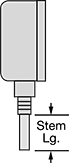
| Dial Diameter | Pipe Size | °F | °C | Environment Temp. Range, °F | Process Temp. Range, °F | Case Color | Mounting Orientation | Stem Lg. | Shoulder Lg. | Each | |
Bottom Connection | |||||||||||
NPT Male | |||||||||||
| 3 1/4" | 1/2 | 70° to 320° | 20° to 160° | -40° to 140° | 70° to 320° | Black | Any | 2" | __ | 0000000 | 000000 |
Center Back Connection | |||||||||||
NPT Male | |||||||||||
| 2 1/2" | 1/4 | 70° to 320° | 20° to 160° | -40° to 140° | 70° to 320° | Black | Any | 1" | __ | 0000000 | 00000 |
| 2 1/2" | 1/4 | 70° to 320° | 20° to 160° | -40° to 140° | 70° to 320° | Black | Any | 1" | 2" | 0000000 | 00000 |
| 2 1/2" | 1/4 | 70° to 320° | 20° to 160° | -40° to 140° | 70° to 320° | Black | Any | 1 1/2" | 2" | 0000000 | 00000 |
| 3 1/4" | 1/2 | 70° to 320° | 20° to 160° | -40° to 140° | 70° to 320° | Black | Any | 2" | __ | 0000000 | 00000 |
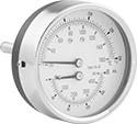
Large-Dial High-Accuracy Pressure Gauges


Read your pressure from a distance with these large-dial gauges. Use them with pumps, filters, regulators, and in process lines to measure and display pressure. They are suitable for critical processes that require high accuracy, such as hydraulic and laboratory applications. Mount gauges with the dial face upright.
Gauges with aluminum case have better corrosion resistance than gauges with steel case.
![]() For technical drawings and 3-D models, click on a part number.
For technical drawings and 3-D models, click on a part number.
- For Use With: Air, Water, and Hydraulic Fluid
- Accuracy: ±1% Full Scale (Grade 1A)
Available Pressure Ranges | ||
|---|---|---|
| Pressure Range, psi | Graduation Marks, psi | Numeric Increments, psi |
| 0 to 30 | 0.5 | 5 |
| 0 to 60 | 1 | 10 |
| 0 to 100 | 2 | 20 |
| 0 to 200 | 2 | 20 |
| 0 to 300 | 5 | 50 |
| 0 to 400 | 4 | 50 |
| 0 to 600 | 10 | 50 |
Mounting | Bolt | Flange | Bottom Connection (Flange Mount) | ||||||||||
|---|---|---|---|---|---|---|---|---|---|---|---|---|---|
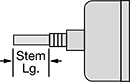
| Dial Diameter | Pipe Size | Environment Temp. Range, °F | Process Temp. Range, °F | Case Color | Orientation | Fasteners Included | Circle Dia. | Hole Dia. | No. of Holes | Location | OD | Each | |
NPT Male | |||||||||||||
| 8 1/2" | 1/4 | -40° to 150° | -40° to 150° | Black | Upright | No | 9 5/8" | 13/64" | 3 | Back | 10 1/4" | 0000000 | 0000000 |
- For Use With: Air, Water, and Hydraulic Fluid
- Accuracy: ±1% Full Scale (Grade 1A)
Available Pressure Ranges | |||||
|---|---|---|---|---|---|
Pressure Range | Graduation Marks | Numeric Increments | |||
| psi | bar | psi | bar | psi | bar |
| 0 to 30 | 0 to 2.06 | 0.5 | 0.02 | 5 | 0.2 |
| 0 to 60 | 0 to 4.1 | 1 | 0.05 | 10 | 0.5 |
| 0 to 100 | 0 to 6.8 | 1 | 0.1 | 10 | 1 |
| 0 to 200 | 0 to 13.6 | 2 | 0.2 | 20 | 2 |
| 0 to 300 | 0 to 20.6 | 5 | 0.2 | 50 | 2 |
| 0 to 400 | 0 to 27.5 | 5 | 0.5 | 50 | 5 |
| 0 to 600 | 0 to 41 | 10 | 0.5 | 100 | 5 |
Bottom Connection | |||||||
|---|---|---|---|---|---|---|---|
| Dial Diameter | Pipe Size | Environment Temp. Range, °F | Process Temp. Range, °F | Case Color | Mounting Orientation | Each | |
NPT Male | |||||||
| 10" | 1/2 | -40° to 140° | -40° to 140° | Black | Upright | 0000000 | 0000000 |
Level Indicators with Shut-Off Valve


Shut-off valves stop flow so you can clean and replace gauge glass without removing these indicators from your equipment.
316 stainless steel indicators are more corrosion resistant than brass or bronze indicators. They have a stainless steel drain valve and be used on expansion tanks.
Indicators with needle stem have a stem in the lower shut-off valve to clear the orifice as the valve closes.
Indicators with automatic shut-off will temporarily close if the gauge glass breaks. The valves must be closed manually for permanent shut-off.
![]() For technical drawings and 3-D models, click on a part number.
For technical drawings and 3-D models, click on a part number.
Level Indicators | |||||||||||||||
|---|---|---|---|---|---|---|---|---|---|---|---|---|---|---|---|
Temp. Range, °F | Replacement Glass | ||||||||||||||
| Connection Ctr.-to-Ctr. | Overall Ht. | Window Ht. | Body Wd. | Drain Cock Dia. | Max. Pressure | Max. Steam Pressure | Min. | Max. | For Use With | No. of Guard Rods | Specifications Met | Each | Each | ||
Bronze | |||||||||||||||
3/8 NPT Male Thread with Needle Stem | |||||||||||||||
| 11 1/4" | 13 5/8" | 7" | 3 7/8" | 7/16" | 400 psi @ 70° F | 200 psi @ 400° F | 35° | 400° | Water, Hydraulic Fluid, Salt Water, Steam | 2 | __ | 0000000 | 0000000 | 0000000 | 000000 |
1/2 NPT Male Thread with Needle Stem | |||||||||||||||
| 13 1/4" | 15 5/8" | 9" | 3 15/16" | 7/16" | 400 psi @ 70° F | 200 psi @ 400° F | 35° | 400° | Water, Hydraulic Fluid, Salt Water, Steam | 2 | __ | 0000000 | 000000 | 0000000 | 00000 |
1/2 NPT Male Thread with Needle Stem and Automatic Shut-Off | |||||||||||||||
| 13 1/4" | 15 5/8" | 9" | 3 15/16" | 1/4" | 400 psi @ 70° F | 200 psi @ 400° F | 35° | 400° | Water, Hydraulic Fluid, Salt Water, Steam | 2 | __ | 0000000 | 000000 | 0000000 | 00000 |
3/4 NPT Male Thread with Needle Stem | |||||||||||||||
| 17 1/2" | 20" | 13" | 4 3/16" | 7/16" | 370 psi @ 70° F | 200 psi @ 400° F | 35° | 400° | Water, Hydraulic Fluid, Salt Water, Steam | 2 | __ | 0000000 | 000000 | 0000000 | 00000 |
3/4 NPT Male Thread with Needle Stem and Automatic Shut-Off | |||||||||||||||
| 17 1/2" | 20" | 13" | 4 3/16" | 7/16" | 370 psi @ 70° F | 200 psi @ 400° F | 35° | 400° | Water, Hydraulic Fluid, Salt Water, Steam | 2 | __ | 0000000 | 000000 | 0000000 | 00000 |
Brass | |||||||||||||||
1/2 NPT Male Thread with Ball-Valve-Style Drain and Automatic Shut-Off | |||||||||||||||
| 14" | 16 1/4" | 9" | 4 5/8" | 1/4" | 400 psi @ 70° F | 200 psi @ 400° F | 35° | 400° | Water, Hydraulic Fluid, Salt Water, Steam | 4 | __ | 0000000 | 000000 | 0000000 | 00000 |
1/2 NPT Male Thread with Ball-Valve-Style Drain | |||||||||||||||
| 14" | 16 1/4" | 9" | 4 5/8" | 1/4" | 400 psi @ 70° F | 200 psi @ 400° F | 35° | 400° | Water, Hydraulic Fluid, Salt Water, Steam | 4 | __ | 0000000 | 000000 | 0000000 | 00000 |
3/4 NPT Male Thread with Ball-Valve-Style Drain | |||||||||||||||
| 18" | 20 1/4" | 13" | 4 5/16" | 1/4" | 370 psi @ 70° F | 200 psi @ 400° F | 35° | 400° | Water, Hydraulic Fluid, Salt Water, Steam | 4 | __ | 0000000 | 000000 | 0000000 | 00000 |
3/4 NPT Male Thread with Ball-Valve-Style Drain and Automatic Shut-Off | |||||||||||||||
| 18" | 20 1/4" | 13" | 4 5/16" | 1/4" | 370 psi @ 70° F | 200 psi @ 400° F | 35° | 400° | Water, Hydraulic Fluid, Salt Water, Steam | 4 | __ | 0000000 | 000000 | 0000000 | 00000 |
316 Stainless Steel | |||||||||||||||
1/2 NPT Male Thread with Needle Stem | |||||||||||||||
| 14" | 15 3/4" | 10 1/4" | 3 15/16" | 7/16" | 250 psi @ 400° F | 250 psi @ 400° F | 35° | 400° | Water, Hydraulic Fluid, Steam | 2 | __ | 000000 | 000000 | 0000000 | 00000 |
1/2 NPT Male Thread with Ball-Valve-Style Drain and Automatic Shut-Off | |||||||||||||||
| 14" | 18 1/16" | 10" | 4 7/8" | 1/4" | 410 psi @ 70° F | 305 psi @ 400° F | 35° | 400° | Water, Hydraulic Fluid, Acetic Acid, Alcohol-Based Solvents, Ketone, Steam | 4 | ASME BPVC.I | 0000000 | 00000000 | 0000000 | 00000 |
3/4 NPT Male Thread with Needle Stem | |||||||||||||||
| 14" | 15 3/4" | 10 1/4" | 3 7/8" | 7/16" | 250 psi @ 400° F | 250 psi @ 400° F | 35° | 400° | Water, Hydraulic Fluid, Steam | 2 | __ | 000000 | 000000 | 0000000 | 00000 |
3/4 NPT Male Thread with Ball-Valve-Style Drain and Automatic Shut-Off | |||||||||||||||
| 18" | 22 1/16" | 12" | 4 13/16" | 1/4" | 370 psi @ 70° F | 280 psi @ 400° F | 35° | 400° | Water, Hydraulic Fluid, Acetic Acid, Alcohol-Based Solvents, Ketone, Steam | 4 | ASME BPVC.I | 0000000 | 00000000 | 0000000 | 00000 |
Heavy Duty Level Indicators


Monitor liquid level in applications that have vibration, high pressures, and high temperatures. These indicators have steel chambers, glass windows, and seals made of fiber and SBR rubber to resist corrosion and withstand higher temperatures than other level indicators. Use them with a wide variety of liquids, such as petroleum, chemicals, and natural gas. All meet ASME BPVC.VIII.1 safety standards for pressure vessels, so they’re approved for use in low-pressure water and steam applications too. Their gauge is made of reflex glass, which shows the level of liquid behind the glass, but not the liquid’s color or any particulates in it. Also known as armored level gauges.
Add shut-off valves to stop flow with the turn of a wheel. They help you access indicators in order to clean or replace the glass or the entire indicator. These valves also stop flow automatically if the indicator glass breaks, preventing the loss of fluid. However, for permanent shut-off you must close them manually. Put one valve on top of your indicator and one on the bottom for a 90° connection between the indicator and your tank. To connect the female threads on your indicator to the female gauge threads on the shut-off valve, use a male pipe nipple (not included).
![]() For technical drawings and 3-D models, click on a part number.
For technical drawings and 3-D models, click on a part number.
Indicators | Shut-Off Valves | Replacement Glass | Replacement Gaskets | |||||||||||
|---|---|---|---|---|---|---|---|---|---|---|---|---|---|---|
| Glass Size | Connection Center-to-Center | Overall Height | Window Height | Body Width | Maximum Pressure | Temperature Range, °F | Each | Each | Each | Each | ||||
Steel Indicator with Reflex Glass | ||||||||||||||
1/2 NPT Female Thread | ||||||||||||||
| 4 | 8 1/4" | 16 1/2" | 6 3/4" | 3 3/4" | 2,725 psi @ 70° F | -20° to 600° | 00000000 | 0000000 | 00000000 | 0000000 | 00000000 | 000000 | 00000000 | 00000 |
| 5 | 9 3/8" | 18 3/4" | 7 7/8" | 3 3/4" | 2,630 psi @ 70° F | -20° to 600° | 00000000 | 00000000 | 00000000 | 000000 | 00000000 | 00000 | 00000000 | 0000 |
| 6 | 10 5/8" | 10 5/8" | 9 1/8" | 3 3/4" | 2,535 psi @ 70° F | -20° to 600° | 00000000 | 000000 | 00000000 | 000000 | 00000000 | 00000 | 00000000 | 0000 |
| 7 | 11 3/4" | 11 3/4" | 10 1/4" | 3 3/4" | 2,440 psi @ 70° F | -20° to 600° | 00000000 | 000000 | 00000000 | 000000 | 00000000 | 00000 | 00000000 | 0000 |
| 8 | 13 3/8" | 13 3/8" | 11 7/8" | 3 3/4" | 2,345 psi @ 70° F | -20° to 600° | 00000000 | 000000 | 00000000 | 000000 | 00000000 | 00000 | 00000000 | 0000 |
| 9 | 14 1/8" | 14 1/8" | 12 5/8" | 3 3/4" | 2,250 psi @ 70° F | -20° to 600° | 00000000 | 000000 | 00000000 | 000000 | 00000000 | 00000 | 00000000 | 0000 |
Gauge Glass for Heavy Duty Level Indicators
Use this gauge glass with heavy duty level indicators.
Reflex glass shows the level of liquid behind it, but you won’t see the liquid’s color or the particulates in it.
Transparent glass helps you monitor the color of liquid and any particulates in it, in addition to the liquid’s level. Use two pieces of this glass in your indicator; the liquid flows between them, so you see straight through.
Use gaskets to seal the glass.
![]() For technical drawings and 3-D models, click on a part number.
For technical drawings and 3-D models, click on a part number.
Gauge Glass | ||||||||||||
|---|---|---|---|---|---|---|---|---|---|---|---|---|
Max. Pressure | Temp. Range, °F | Gaskets | ||||||||||
| Glass Size | Ht. | Wd. | Thick. | Liquid | Steam | Min. | Max. | Specifications Met | Each | Each | ||
Reflex Glass | ||||||||||||
| 4 | 7 1/2" | 1 5/16" | 11/16" | 4,000 psi @ 100° F | 500 psi @ 425° F | -415° | 470° | DIN 7080, DIN 7081, JIS B 8211, MIL-G-16356 | 00000000 | 000000 | 00000000 | 00000 |
| 5 | 8 5/8" | 1 5/16" | 11/16" | 4,000 psi @ 100° F | 500 psi @ 425° F | -415° | 470° | DIN 7080, DIN 7081, JIS B 8211, MIL-G-16356 | 00000000 | 00000 | 00000000 | 0000 |
| 6 | 9 7/8" | 1 5/16" | 11/16" | 4,000 psi @ 100° F | 500 psi @ 425° F | -415° | 470° | DIN 7080, DIN 7081, JIS B 8211, MIL-G-16356 | 00000000 | 00000 | 00000000 | 0000 |
| 7 | 11" | 1 5/16" | 11/16" | 4,000 psi @ 100° F | 500 psi @ 425° F | -415° | 470° | DIN 7080, DIN 7081, JIS B 8211, MIL-G-16356 | 00000000 | 00000 | 00000000 | 0000 |
| 8 | 12 5/8" | 1 5/16" | 11/16" | 4,000 psi @ 100° F | 500 psi @ 425° F | -415° | 470° | DIN 7080, DIN 7081, JIS B 8211, MIL-G-16356 | 00000000 | 00000 | 00000000 | 0000 |
| 9 | 13 3/8" | 1 5/16" | 11/16" | 4,000 psi @ 100° F | 500 psi @ 425° F | -415° | 470° | DIN 7080, DIN 7081, JIS B 8211, MIL-G-16356 | 00000000 | 00000 | 00000000 | 0000 |
Transparent Glass | ||||||||||||
| 4 | 7 1/2" | 1 5/16" | 11/16" | 1,940 psi @ 100° F | 1,620 psi @ 425° F | -20° | 600° | __ | 000000000 | 000000 | 00000000 | 0000 |
| 5 | 8 5/8" | 1 5/16" | 11/16" | 1,750 psi @ 100° F | 1,460 psi @ 425° F | -20° | 600° | __ | 000000000 | 000000 | 00000000 | 0000 |
| 6 | 9 7/8" | 1 5/16" | 11/16" | 1,565 psi @ 100° F | 1,305 psi @ 425° F | -20° | 600° | __ | 000000000 | 000000 | 00000000 | 0000 |
| 7 | 11" | 1 5/16" | 11/16" | 1,375 psi @ 100° F | 1,145 psi @ 425° F | -20° | 600° | __ | 000000000 | 000000 | 00000000 | 0000 |
| 8 | 12 5/8" | 1 5/16" | 11/16" | 1,190 psi @ 100° F | 990 psi @ 425° F | -20° | 600° | __ | 000000000 | 000000 | 00000000 | 0000 |
| 9 | 13 3/8" | 1 5/16" | 11/16" | 1,000 psi @ 100° F | 835 psi @ 425° F | -20° | 600° | __ | 000000000 | 000000 | 00000000 | 0000 |