


Expansion Tanks for Drinking Water


--254778721a21610474326-p9@halfx_637460495290491699.png?ver=imagenotfound)
These tanks meet NSF/ANSI Standard 61 for use with drinking (potable) water. Use them to accommodate the expansion of heated water and provide a cushion of compressed air in closed water-heating systems. All of these tanks have a diaphragm, which completely separates air and water. They prevent water loss by eliminating the need to expel hot water from systems during each heating cycle.
![]() For technical drawings and 3-D models, click on a part number.
For technical drawings and 3-D models, click on a part number.
Tank End (E1) | ||||||||||||
|---|---|---|---|---|---|---|---|---|---|---|---|---|
| Capacity, gal. | Dia. | Overall Lg. | Connection Pipe Size | Pipe Connection Thread Type | Pipe Connection Gender | Wall Gauge, ga. | Max. Temp., °F | Max. Pressure, psi | Diaphragm Material | Specifications Met | Each | |
Beige-Painted Steel | ||||||||||||
| 2.1 | 8" | 11" | 3/4 | NPT | Male | 16 | 200° | 150 | Butyl Rubber | NSF/ANSI 61 | 000000 | 000000 |
| 4.5 | 10 1/2" | 13 1/2" | 3/4 | NPT | Male | 16 | 200° | 150 | Butyl Rubber | NSF/ANSI 61 | 000000 | 000000 |
| 8.5 | 12 1/2" | 19 3/16" | 3/4 | NPT | Male | 16 | 200° | 150 | Butyl Rubber | NSF/ANSI 61 | 000000 | 000000 |
Expansion Tanks for Lubricants


A rolling rubber diaphragm maintains tank pressure at or near 0 psi, which extends seal life to help keep lubricants clean. Use these tanks to accommodate the expansion of heated lubricants and provide a cushion of compressed air in closed lubricant-heating systems. They prevent lubricant loss by eliminating the need to expel hot lubricant from systems during each heating cycle.
![]() For technical drawings and 3-D models, click on a part number.
For technical drawings and 3-D models, click on a part number.
Tank End | ||||||||||||
|---|---|---|---|---|---|---|---|---|---|---|---|---|
| Capacity, cu. in. | Connection Pipe Size | Pipe Connection Thread Type | Pipe Connection Gender | Stem Lg. | Dia. | Overall Lg. | Wall Gauge, ga. | Max. Temp., °F | Max. Pressure, psi | Diaphragm Material | Each | |
304 Stainless Steel | ||||||||||||
| 25 | 1/2 | NPT | Male | 1" | 4 1/16" | 3 3/4" | 20 | 350° | 15 | Fluoroelastomer Rubber | 0000000 | 0000000 |
| 25 | 3/4 | NPT | Male | 1 1/4" | 4 1/16" | 3 3/4" | 20 | 350° | 15 | Fluoroelastomer Rubber | 0000000 | 000000 |
| 25 | 3/8 | NPT | Male | 7/8" | 4 1/16" | 3 3/4" | 20 | 350° | 15 | Fluoroelastomer Rubber | 0000000 | 000000 |
Bladder-Style Hydraulic Accumulators
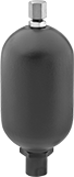
Charge these accumulators to the pressure you need, and they will help a system maintain a constant pressure during pump failure. Mount accumulators within 25° of vertical. UN/UNF (SAE Straight) thread connections have straight threads and are also known as O-ring Boss fittings.
Note: For safety, do not disassemble accumulators while they're under pressure.
Use a charging and gauging kit to increase or decrease an accumulator's charge.
![]() For technical drawings and 3-D models, click on a part number.
For technical drawings and 3-D models, click on a part number.
Accumulators | |||||||||||||||
|---|---|---|---|---|---|---|---|---|---|---|---|---|---|---|---|
Inlet/Outlet Connection for Hydraulic Fluid— UN/UNF (SAE Straight) | Inlet/Outlet Connection for Nitrogen | Body | Repl. Bladder Bags | ||||||||||||
| Cap. | Max. Flow Rate, gpm | Max. Pressure, psi | Thread Size | Gender | Dash Size | Valve Type | Gender | O'all Ht. | Ht. | Dia. | Mounting Orientation | Each | Each | ||
Steel Body with Buna-N Rubber Bag and Seal | |||||||||||||||
| 16 fl. oz. | 40 | 3,000 | 1 1/16"-12 | Female | 12 | Schrader | Male | 10 3/4" | 6 7/8" | 3 3/8" | Vertical | 00000000 | 000000000 | 00000000 | 0000000 |
| 32 fl. oz. | 40 | 3,000 | 1 5/16"-12 | Female | 16 | Schrader | Male | 11 1/8" | 7 5/8" | 4 1/2" | Vertical | 00000000 | 00000000 | 00000000 | 000000 |
| 1 gal. | 150 | 3,000 | 1 5/8"-12 | Female | 20 | Schrader | Male | 17" | 11 3/8" | 6 3/4" | Vertical | 00000000 | 00000000 | 00000000 | 000000 |
| 2 1/2 gal. | 220 | 3,000 | 1 7/8"-12 | Female | 24 | Schrader | Male | 21 3/8" | 15 1/2" | 9" | Vertical | 00000000 | 00000000 | 00000000 | 000000 |
| 5 gal. | 220 | 3,000 | 1 7/8"-12 | Female | 24 | Schrader | Male | 33 3/8" | 27 1/2" | 9" | Vertical | 00000000 | 00000000 | 00000000 | 000000 |
| Charging and Gauging Kits | 00000000 | Each | 0000000 |
Charged Bladder-Style Hydraulic Accumulators
These accumulators come with a charge of nitrogen and are ready to use. They help a system maintain a constant pressure during pump failure. Mount accumulators within 25° of vertical. UN/UNF (SAE Straight) thread connections have straight threads and are also known as O-ring Boss fittings.
Note: For safety, do not disassemble accumulators while they're under pressure.
Use a charging and gauging kit to increase or decrease an accumulator's charge.
![]() For technical drawings and 3-D models, click on a part number.
For technical drawings and 3-D models, click on a part number.
Accumulators | ||||||||||||||||
|---|---|---|---|---|---|---|---|---|---|---|---|---|---|---|---|---|
Inlet/Outlet Connection for Hydraulic Fluid— UN/UNF (SAE Straight) | Inlet/Outlet Connection for Nitrogen | Body | Repl. Bladder Bags | |||||||||||||
| Cap. | Max. Flow Rate, gpm | Max. Pressure, psi | Nitrogen Charge, psi | Thread Size | Gender | Dash Size | Valve Type | Gender | O'all Ht. | Ht. | Dia. | Mounting Orientation | Each | Each | ||
Steel Body with Buna-N Rubber Bag and Seal | ||||||||||||||||
| 16 fl. oz. | 40 | 3,000 | 1,000 | 1 1/16"-12 | Female | 12 | Schrader | Male | 10 3/4" | 6 7/8" | 3 3/8" | Vertical | 00000000 | 0000000 | 00000000 | 0000000 |
| 32 fl. oz. | 40 | 3,000 | 1,000 | 1 5/16"-12 | Female | 16 | Schrader | Male | 11 1/8" | 7 5/8" | 4 1/2" | Vertical | 00000000 | 00000000 | 00000000 | 000000 |
| 1 gal. | 150 | 3,000 | 2,100 | 1 5/8"-12 | Female | 20 | Schrader | Male | 17" | 11 3/8" | 6 3/4" | Vertical | 00000000 | 00000000 | 00000000 | 000000 |
| 2 1/2 gal. | 220 | 3,000 | 2,100 | 1 7/8"-12 | Female | 24 | Schrader | Male | 21 3/8" | 15 1/2" | 9" | Vertical | 00000000 | 00000000 | 00000000 | 000000 |
| 5 gal. | 220 | 3,000 | 2,100 | 1 7/8"-12 | Female | 24 | Schrader | Male | 33 3/8" | 27 1/2" | 9" | Vertical | 00000000 | 00000000 | 00000000 | 000000 |
| Charging and Gauging Kits | 00000000 | Each | 0000000 |
Sealed Hydraulic Accumulators
Charge these accumulators to the pressure you need, and they will help a system maintain a constant pressure during pump failure. Mount them in any orientation. UN/UNF (SAE Straight) thread connections have straight threads and are also known as O-ring Boss fittings.
Note: For safety, do not disassemble accumulators while they're under pressure.
Diaphragm accumulators have bags that can't be replaced.
Use a charging and gauging kit to increase or decrease an accumulator’s charge.
![]() For technical drawings and 3-D models, click on a part number.
For technical drawings and 3-D models, click on a part number.

Inlet/Outlet Connection for Hydraulic Fluid— UN/UNF (SAE Straight) | Inlet/Outlet Connection for Nitrogren | Body | |||||||||||
|---|---|---|---|---|---|---|---|---|---|---|---|---|---|
| Cap., fl. oz. | Max. Flow Rate, gpm | Max. Pressure, psi | Thread Size | Gender | Dash Size | Valve Type | Gender | O'all Ht. | Ht. | Dia. | Mounting Orientation | Each | |
Steel Body with Buna-N Rubber Diaphragm | |||||||||||||
| 16 1/2 | 25 | 3,000 | 3/4"-16 | Female | 08 | Schrader | Male | 6 7/8" | 4 3/8" | 4 1/8" | Any Position | 0000000 | 0000000 |
| 33 1/2 | 25 | 3,000 | 3/4"-16 | Female | 08 | Schrader | Male | 7 7/8" | 5 3/8" | 5 3/8" | Any Position | 0000000 | 000000 |
| 66 1/2 | 40 | 3,000 | 1 1/16"-12 | Female | 12 | Schrader | Male | 9 1/4" | 6 13/16" | 6 5/8" | Any Position | 0000000 | 000000 |
| Charging and Gauging Kits | 00000000 | Each | 0000000 |
Inlet/Outlet Connection for Hydraulic Fluid— UN/UNF (SAE Straight) | Inlet/Outlet Connection for Nitrogren | Body | ||||||||||||
|---|---|---|---|---|---|---|---|---|---|---|---|---|---|---|
| Cap., fl. oz. | Max. Flow Rate, gpm | Max. Pressure, psi | Thread Size | Gender | Dash Size | Valve Type | Gender | O'all Ht. | Ht. | Dia. | Bore Dia. | Mounting Orientation | Each | |
Steel Body with Buna-N Rubber Seal | ||||||||||||||
| 16 | 100 | 4,000 | 3/4"-16 | Female | 08 | Schrader | Male | 13 3/8" | 12 7/16" | 2 3/8" | 2" | Any Position | 0000000 | 0000000 |
| 32 | 100 | 4,000 | 3/4"-16 | Female | 08 | Schrader | Male | 21 7/8" | 20 15/16" | 2 3/8" | 2" | Any Position | 0000000 | 000000 |
| Charging and Gauging Kits | 00000000 | Each | 0000000 |
Charged Sealed Hydraulic Accumulators
These accumulators come with a charge of nitrogen and are ready to use. They help a system maintain a constant pressure during pump failure. Mount these accumulators in any orientation. UN/UNF (SAE Straight) thread connections have straight threads and are also known as O-ring Boss fittings.
Note: For safety, do not disassemble accumulators while they're under pressure.
Diaphragm accumulators have bags that can't be replaced.
Use a charging and gauging kit to increase or decrease an accumulator’s charge.
![]() For technical drawings and 3-D models, click on a part number.
For technical drawings and 3-D models, click on a part number.
Inlet/Outlet Connection for Hydraulic Fluid— UN/UNF (SAE Straight) | Inlet/Outlet Connection for Nitrogen | Body | ||||||||||||
|---|---|---|---|---|---|---|---|---|---|---|---|---|---|---|
| Cap., fl. oz. | Max. Flow Rate, gpm | Max. Pressure, psi | Nitrogen Charge, psi | Thread Size | Gender | Dash Size | Valve Type | Gender | O'all Ht. | Ht. | Dia. | Mounting Orientation | Each | |
Steel Body with Buna-N Rubber Diaphragm | ||||||||||||||
| 16 1/2 | 25 | 3,000 | 1,000 | 3/4"-16 | Female | 08 | Schrader | Male | 6 7/8" | 4 3/8" | 4 1/8" | Any Position | 0000000 | 0000000 |
| 66 1/2 | 40 | 3,000 | 1,000 | 1 1/16"-12 | Female | 12 | Schrader | Male | 9 1/4" | 6 13/16" | 6 5/8" | Any Position | 0000000 | 00000000 |
| Charging and Gauging Kits | 00000000 | Each | 0000000 |
Inlet/Outlet Connection for Hydraulic Fluid— UN/UNF (SAE Straight) | Inlet/Outlet Connection for Nitrogen | Body | |||||||||||||
|---|---|---|---|---|---|---|---|---|---|---|---|---|---|---|---|
| Cap., fl. oz. | Max. Flow Rate, gpm | Max. Pressure, psi | Nitrogen Charge, psi | Thread Size | Gender | Dash Size | Valve Type | Gender | O'all Ht. | Ht. | Dia. | Bore Dia. | Mounting Orientation | Each | |
Steel Body with Buna-N Rubber Seal | |||||||||||||||
| 16 | 100 | 4,000 | 1,000 | 3/4"-16 | Female | 08 | Schrader | Male | 13 3/8" | 12 7/16" | 2 3/8" | 2" | Any Position | 0000000 | 0000000 |
| 32 | 100 | 4,000 | 1,000 | 3/4"-16 | Female | 08 | Schrader | Male | 21 7/8" | 20 15/16" | 2 3/8" | 2" | Any Position | 0000000 | 000000 |
| Charging and Gauging Kits | 00000000 | Each | 0000000 |