Filter by
System of Measurement
For Motion
Mechanical Finish
Step Length
Edge Type
Hardness Rating
Hardness
Export Control Classification Number (ECCN)
REACH
DFARS Specialty Metals
RoHS
About Shafts
More
Step-Down Rotary Shafts
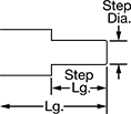
A shoulder near the end of the shaft provides a stop for gears, sprockets, and bearings. The edges are chamfered to remove sharp corners, reducing damage to bearings, housings, and other components during installation. All are turned, ground, and polished to tight diameter and straightness tolerances.
1045 carbon steel shafts balance high strength and good machinability, making them ideal for general purpose use. They are stronger than aluminum and stainless steel shafts but not as corrosion resistant. 303 stainless steel shafts are more corrosion resistant than steel shafts but also more difficult to machine.
Step Down × Straight End

Step-Down End × Straight End

Step | |||||||||
|---|---|---|---|---|---|---|---|---|---|
| Lg. | Lg. Tolerance | Dia. | Lg. | Straightness Tolerance | Edge Type | Hardness Rating | Hardness | Each | |
Inch—1045 Carbon Steel | |||||||||
3/4" Dia. (Tolerance: -0.001" to 0") | |||||||||
| 6" | -0.005" to 0.005" | 1/2" | 3" | 0.003" per ft. | Chamfered | Medium | Brinell 150 | 000000 | 000000 |
| 9" | -0.005" to 0.005" | 1/2" | 3" | 0.003" per ft. | Chamfered | Medium | Brinell 150 | 000000 | 00000 |
| 12" | -0.005" to 0.005" | 1/2" | 3" | 0.003" per ft. | Chamfered | Medium | Brinell 150 | 000000 | 00000 |
1" Dia. (Tolerance: -0.001" to 0") | |||||||||
| 6" | -0.005" to 0.005" | 3/4" | 3" | 0.003" per ft. | Chamfered | Medium | Brinell 150 | 000000 | 00000 |
| 9" | -0.005" to 0.005" | 3/4" | 3" | 0.003" per ft. | Chamfered | Medium | Brinell 150 | 000000 | 00000 |
| 12" | -0.005" to 0.005" | 3/4" | 3" | 0.003" per ft. | Chamfered | Medium | Brinell 150 | 000000 | 00000 |
Inch—303 Stainless Steel | |||||||||
3/4" Dia. (Tolerance: -0.001" to 0") | |||||||||
| 6" | -0.005" to 0.005" | 1/2" | 3" | 0.003" per ft. | Chamfered | Medium | Brinell 160 | 0000000 | 00000 |
| 9" | -0.005" to 0.005" | 1/2" | 3" | 0.003" per ft. | Chamfered | Medium | Brinell 160 | 0000000 | 00000 |
| 12" | -0.005" to 0.005" | 1/2" | 3" | 0.003" per ft. | Chamfered | Medium | Brinell 160 | 0000000 | 00000 |
1" Dia. (Tolerance: -0.001" to 0") | |||||||||
| 6" | -0.005" to 0.005" | 3/4" | 3" | 0.003" per ft. | Chamfered | Medium | Brinell 160 | 0000000 | 00000 |
| 9" | -0.005" to 0.005" | 3/4" | 3" | 0.003" per ft. | Chamfered | Medium | Brinell 160 | 0000000 | 00000 |
| 12" | -0.005" to 0.005" | 3/4" | 3" | 0.003" per ft. | Chamfered | Medium | Brinell 160 | 0000000 | 00000 |
Step-Down on Both Ends

Step-Down on Both Ends

Step | |||||||||
|---|---|---|---|---|---|---|---|---|---|
| Lg. | Lg. Tolerance | Dia. | Lg. | Straightness Tolerance | Edge Type | Hardness Rating | Hardness | Each | |
Inch—1045 Carbon Steel | |||||||||
3/4" Dia. (Tolerance: -0.001" to 0") | |||||||||
| 12" | -0.005" to 0.005" | 1/2" | 3" | 0.003" per ft. | Chamfered | Medium | Brinell 150 | 0000000 | 000000 |
| 18" | -0.005" to 0.005" | 1/2" | 3" | 0.003" per ft. | Chamfered | Medium | Brinell 150 | 0000000 | 00000 |
| 24" | -0.005" to 0.005" | 1/2" | 3" | 0.003" per ft. | Chamfered | Medium | Brinell 150 | 0000000 | 00000 |
1" Dia. (Tolerance: -0.001" to 0") | |||||||||
| 12" | -0.005" to 0.005" | 1/2" | 3" | 0.003" per ft. | Chamfered | Medium | Brinell 150 | 0000000 | 00000 |
| 12" | -0.005" to 0.005" | 3/4" | 3" | 0.003" per ft. | Chamfered | Medium | Brinell 150 | 0000000 | 00000 |
| 18" | -0.005" to 0.005" | 1/2" | 3" | 0.003" per ft. | Chamfered | Medium | Brinell 150 | 0000000 | 00000 |
| 18" | -0.005" to 0.005" | 3/4" | 3" | 0.003" per ft. | Chamfered | Medium | Brinell 150 | 0000000 | 00000 |
| 24" | -0.005" to 0.005" | 1/2" | 3" | 0.003" per ft. | Chamfered | Medium | Brinell 150 | 0000000 | 00000 |
| 24" | -0.005" to 0.005" | 3/4" | 3" | 0.003" per ft. | Chamfered | Medium | Brinell 150 | 0000000 | 00000 |


