


About Timer Relays
More
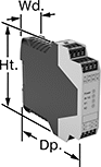
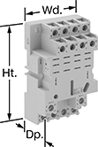
Compact Spade-Terminal Relays
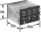

Fit these relays where standard spade-terminal relays are too big. You can connect them three ways. Plug them into a socket (sold separately), connect them with quick-disconnect terminals, or solder wires directly to the terminals. An LED indicator shows you the status of the relay, so you know it’s connected and wired correctly.
Relays that control 2 or more circuits have a lockable test button, so you can test their function. When you press the button, the relay switches contacts. Use this button when checking a relay for proper function before installing it, or when investigating issues with wired relays.
Relay sockets mount directly on 35 mm DIN rail (also known as DIN 3 rail) for fast installation. You can also mount them to a flat surface using screws.
![]() For technical drawings and 3-D models, click on a part number.
For technical drawings and 3-D models, click on a part number.
Relays | Relay Sockets with Screw Terminals | |||||||||||
|---|---|---|---|---|---|---|---|---|---|---|---|---|
| Number of Terminals | Input Voltage | Control Current, mA | Switching Current @ Voltage | Maximum Switching Voltage | Ht. | Wd. | Dp. | Quick-Disconnect Tab Wd. | Each | Each | ||
4 Circuits Controlled with 4 Off (Normally Open) or 4 On (Normally Closed)—4PDT | ||||||||||||
Relay-Socket Mount | ||||||||||||
| 14 | 24V AC | 50 | 8 A @ 120 V AC/24 V DC | 300V AC | 1.1" | 0.9" | 1.6" | 0.11" | 000000000 | 000000 | 0000000 | 000000 |
| 14 | 24V AC | 63 | 15 A @ 120 V AC 12 A @ 24 V DC | 300V AC | 1.1" | 1.6" | 1.6" | 0.187" | 00000000 | 00000 | 0000000 | 00000 |
| 14 | 120V AC | 10 | 8 A @ 120 V AC/24 V DC | 300V AC | 1.1" | 0.9" | 1.6" | 0.11" | 000000000 | 00000 | 0000000 | 00000 |
| 14 | 120V AC | 13 | 15 A @ 120 V AC 12 A @ 24 V DC | 300V AC | 1.1" | 1.6" | 1.6" | 0.187" | 00000000 | 00000 | 0000000 | 00000 |
| 14 | 240V AC | 5 | 8 A @ 120 V AC/24 V DC | 300V AC | 1.1" | 0.9" | 1.6" | 0.11" | 000000000 | 00000 | 0000000 | 00000 |
| 14 | 240V AC | 6 | 15 A @ 120 V AC 12 A @ 24 V DC | 300V AC | 1.1" | 1.6" | 1.6" | 0.187" | 00000000 | 00000 | 0000000 | 00000 |
| 14 | 12V DC | 92 | 8 A @ 120 V AC/24 V DC | 300V AC | 1.1" | 0.9" | 1.6" | 0.11" | 000000000 | 00000 | 0000000 | 00000 |
| 14 | 12V DC | 125 | 15 A @ 120 V AC 12 A @ 24 V DC | 300V AC | 1.1" | 1.6" | 1.6" | 0.187" | 00000000 | 00000 | 0000000 | 00000 |
| 14 | 24V DC | 6 | 15 A @ 120 V AC 12 A @ 24 V DC | 300V AC | 1.1" | 1.6" | 1.6" | 0.187" | 00000000 | 00000 | 0000000 | 00000 |
| 14 | 24V DC | 46 | 8 A @ 120 V AC/24 V DC | 300V AC | 1.1" | 0.9" | 1.6" | 0.11" | 000000000 | 00000 | 0000000 | 00000 |
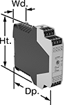
DIN-Rail Mount Interface Relays

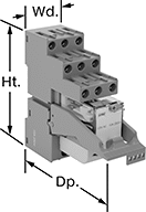
Isolate input and output circuits to prevent damage from voltage spikes, reduce signal interference, and amplify signal. These relays interface between your controller and components—they receive a signal from the controller to switch power on or off to the components. All have an LED indicator that shows you if your switch is actuated, so you know it’s connected and wired correctly. Use them to communicate signals to devices like motors or sensors. Mount them on 35 mm DIN rail (also known as DIN 3 rail).
Relays with spring-clamp terminals connect and disconnect to wires without needing to turn screws. Because there is no screw, these connections have less risk of loosening over time than screw terminals, even when there is vibration.
Relays with PLC output protection prevent voltage spikes created by the relay from damaging the output channel on your programmable logic controller (PLC).
![]() For technical drawings and 3-D models, click on a part number.
For technical drawings and 3-D models, click on a part number.
Relays with Relay Sockets | Replacement Relays | |||||||||||
|---|---|---|---|---|---|---|---|---|---|---|---|---|
| Number of Terminals | Input Voltage | Control Current, mA | Switching Current @ 240V AC | hp @ Switching Voltage | Ht. | Wd. | Dp. | Features | Each | Each | ||
4 Circuits Controlled with 4 Off (Normally Open) or 4 On (Normally Closed)—4PDT | ||||||||||||
With Screw Terminals | ||||||||||||
| 14 | 24V AC | 53 | 7A | 1/8 hp @ 120 V AC | 3.1" | 1.1" | 3.3" | LED Indicator, PLC Output Protection | 00000000 | 000000 | 00000000 | 000000 |
| 14 | 120V AC | 12 | 7A | 1/8 hp @ 120 V AC | 3.1" | 1.1" | 3.3" | LED Indicator, PLC Output Protection | 00000000 | 00000 | 00000000 | 00000 |
| 14 | 12V DC | 86 | 7A | 1/8 hp @ 120 V AC | 3.1" | 1.1" | 3.3" | LED Indicator, PLC Output Protection | 00000000 | 00000 | 00000000 | 00000 |
| 14 | 24V DC | 40 | 7A | 1/8 hp @ 120 V AC | 3.1" | 1.1" | 3.3" | LED Indicator, PLC Output Protection | 00000000 | 00000 | 00000000 | 00000 |
With Spring-Clamp Terminals | ||||||||||||
| 14 | 24V AC | 53 | 7A | 1/8 hp @ 120 V AC | 3.9" | 1.2" | 3.3" | LED Indicator, PLC Output Protection | 00000000 | 00000 | 00000000 | 00000 |
| 14 | 12V DC | 86 | 7A | 1/8 hp @ 120 V AC | 3.9" | 1.2" | 3.3" | LED Indicator, PLC Output Protection | 00000000 | 00000 | 00000000 | 00000 |
| 14 | 24V DC | 40 | 7A | 1/8 hp @ 120 V AC | 3.9" | 1.2" | 3.3" | LED Indicator, PLC Output Protection | 00000000 | 00000 | 00000000 | 00000 |
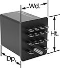
Circuit Board Relays
Smaller than relays with electrical wiring, these relays fit in compact devices. Mount them through holes on circuit boards with their solder pin terminals. Use them to control heaters, fans, and other high-power components from a low-power circuit.
![]() For technical drawings and 3-D models, click on a part number.
For technical drawings and 3-D models, click on a part number.
| Number of Terminals | Input Voltage | Control Current, mA | Switching Current @ Voltage | Max. Switching Voltage | Mechanical Life Cycles | Ht. | Wd. | Dp. | Pin Lg. | Each | |
Mechanical | |||||||||||
|---|---|---|---|---|---|---|---|---|---|---|---|
2 Circuits Controlled with 2 Off (Normally Open)—DPST-NO | |||||||||||
| 14 | 12V DC | 240 | 100 A @ 400 V AC | 400V AC | 1,000,000 | 2.1" | 2.1" | 2.3" | 0.18" | 0000000 | 000000 |
| 14 | 24V DC | 120 | 100 A @ 400 V AC | 400V AC | 1,000,000 | 2.1" | 2.1" | 2.3" | 0.18" | 0000000 | 00000 |
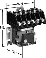
Open-Style Screw Terminal Relays

Optional covers protect contacts from dust and dirt.
Relays | Optional Covers | |||||||||||
|---|---|---|---|---|---|---|---|---|---|---|---|---|
| Number of Terminals | Input Voltage | Control Current, mA | Switching Current @ Voltage | Max. Switching Voltage | hp @ Switching Voltage | Ht. | Wd. | Dp. | Each | Each | ||
4 Circuits Controlled with 4 Off (Normally Open) or 4 On (Normally Closed)—4PDT | ||||||||||||
| 14 | 120V AC | 116 | 35 A @ 120 V AC 20 A @ 24 V DC | 120V AC | 1 hp @ 120 V AC 1 1/2 hp @ 240 V AC | 3.4" | 2.7" | 2.7" | 0000000 | 0000000 | 0000000 | 0000000 |
Circuit Board Safety Relays
Reduce connection errors on circuit boards that control machine guards and other safety devices. Also known as force-guided contact relays, they have contact pairs that won’t close at the same time, even if contacts stick or weld shut. These relays take up less space on a board than those with electrical wiring because their solder pin terminals mount directly through circuit board holes. Use them to control high-power components, such as fans and heaters, from a low-power circuit.
Relays with surge suppression coverage protect sensitive electronics from damage and malfunction by eliminating voltage spikes. Switching off a relay can generate surges of 300 to 500 volts, but a diode within these relays suppresses these surges. An LED indicator on these relays lights up when they’re on, so you know at a glance if they’re wired correctly.
![]() For technical drawings and 3-D models, click on a part number.
For technical drawings and 3-D models, click on a part number.
| Number of Terminals | Input Voltage | Control Current, mA | Switching Current @ Voltage | Max. Switching Voltage | Mechanical Life Cycles | Ht. | Wd. | Dp. | Pin Lg. | Features | Surge Suppression Coverage | Each | |
6 Circuits Controlled with 3 Off (Normally Open) and 3 On (Normally Closed)—6PST-3NO/3NC | |||||||||||||
|---|---|---|---|---|---|---|---|---|---|---|---|---|---|
| 14 | 12V DC | 41 | 6 A @ 240 V AC/30 V DC | 250V AC, 125V DC | 10,000,000 | 0.9" | 0.5" | 2" | 0.14" | Interlocked Opposing Contacts | __ | 0000000 | 000000 |
| 14 | 12V DC | 43 | 6 A @ 240 V AC/30 V DC | 250V AC, 125V DC | 10,000,000 | 0.9" | 0.5" | 2" | 0.14" | Interlocked Opposing Contacts, LED Indicator | Full | 0000000 | 00000 |
| 14 | 24V DC | 20 | 6 A @ 240 V AC/30 V DC | 250V AC, 125V DC | 10,000,000 | 0.9" | 0.5" | 2" | 0.14" | Interlocked Opposing Contacts | __ | 0000000 | 00000 |
| 14 | 24V DC | 22 | 6 A @ 240 V AC/30 V DC | 250V AC, 125V DC | 10,000,000 | 0.9" | 0.5" | 2" | 0.14" | Interlocked Opposing Contacts, LED Indicator | Full | 0000000 | 00000 |
6 Circuits Controlled with 4 Off (Normally Open) and 2 On (Normally Closed)—6PST-4NO/2NC | |||||||||||||
| 14 | 12V DC | 41 | 6 A @ 240 V AC/30 V DC | 250V AC, 125V DC | 10,000,000 | 0.9" | 0.5" | 2" | 0.14" | Interlocked Opposing Contacts | __ | 0000000 | 00000 |
| 14 | 12V DC | 43 | 6 A @ 240 V AC/30 V DC | 250V AC, 125V DC | 10,000,000 | 0.9" | 0.5" | 2" | 0.14" | Interlocked Opposing Contacts, LED Indicator | Full | 0000000 | 00000 |
| 14 | 24V DC | 20 | 6 A @ 240 V AC/30 V DC | 250V AC, 125V DC | 10,000,000 | 0.9" | 0.5" | 2" | 0.14" | Interlocked Opposing Contacts | __ | 0000000 | 00000 |
| 14 | 24V DC | 22 | 6 A @ 240 V AC/30 V DC | 250V AC, 125V DC | 10,000,000 | 0.9" | 0.5" | 2" | 0.14" | Interlocked Opposing Contacts, LED Indicator | Full | 0000000 | 00000 |
6 Circuits Controlled with 5 Off (Normally Open) and 1 On (Normally Closed)—6PST-5NO/1NC | |||||||||||||
| 14 | 12V DC | 41 | 6 A @ 240 V AC/30 V DC | 250V AC, 125V DC | 10,000,000 | 0.9" | 0.5" | 2" | 0.14" | Interlocked Opposing Contacts | __ | 0000000 | 00000 |
| 14 | 12V DC | 43 | 6 A @ 240 V AC/30 V DC | 250V AC, 125V DC | 10,000,000 | 0.9" | 0.5" | 2" | 0.14" | Interlocked Opposing Contacts, LED Indicator | Full | 0000000 | 00000 |
| 14 | 24V DC | 20 | 6 A @ 240 V AC/30 V DC | 250V AC, 125V DC | 10,000,000 | 0.9" | 0.5" | 2" | 0.14" | Interlocked Opposing Contacts | __ | 0000000 | 00000 |
| 14 | 24V DC | 22 | 6 A @ 240 V AC/30 V DC | 250V AC, 125V DC | 10,000,000 | 0.9" | 0.5" | 2" | 0.14" | Interlocked Opposing Contacts, LED Indicator | Full | 0000000 | 00000 |
Safety Relays with Diagnostic Capabilities
Control and diagnose issues with safety-critical circuits. These relays have a microprocessor that monitors safety components, such as emergency stops and light curtains, and sends a signal to stop the operation if a failure is detected and restart when the issue is resolved. They also help with diagnostic tasks because of their feedback circuit, which allows basic relays to communicate their status back to the safety relay. These relays have a duplicate set of input and output signals, so they’ll still stop the controlled device if one of the inputs fails.
IP20 rated, they have recessed terminals which prevent fingers and other objects from touching live circuits. These relays have been tested to multiple safety standards and can help achieve PL, SIL, or CAT system ratings. They also meet ISO and IEC standards for machine safety.
Mount them to 35 mm DIN rail (also known as DIN 3 Rail) for fast installation.
Auxiliary contact blocks (sold separately) allow you to control more components, such as signaling devices or basic relays.
![]() For technical drawings and 3-D models, click on a part number.
For technical drawings and 3-D models, click on a part number.
| Number of Terminals | Input Voltage | Switching Current @ Voltage | Max. Switching Voltage | Ht. | Wd. | Dp. | For Use With | Max. System Safety Rating | Features | Each | |
2 Circuits Controlled | |||||||||||
|---|---|---|---|---|---|---|---|---|---|---|---|
2 Off (Normally Open) | |||||||||||
| 14 | 24V DC | 2 A @ 240 V AC 1.5 A @ 24 V DC | 250V AC | 4.9" | 0.69" | 4.3" | Emergency Stops, Light Curtains | PLe, SIL3, CAT 4, 250V | Auxiliary PNP Output, LED Indicator | 0000000 | 0000000 |

| Number of Terminals | Input Voltage | Switching Current @ Voltage | Max. Switching Voltage | Ht. | Wd. | Dp. | Features | Each | |
5 Safety Outputs | |||||||||
|---|---|---|---|---|---|---|---|---|---|
| 16 | 24V AC, 24V DC | 2.5 A @ 24 V DC 3 A @ 240 V AC | 250V AC, 250V DC | 3.9" | 0.9" | 4.5" | __ | 0000000 | 0000000 |
4 Delayed Safety Outputs | |||||||||
| 16 | 24V DC | 3 A @ 240 V AC 3 A @ 24 V DC | 250V AC, 250V DC | 3.9" | 0.9" | 4.5" | Time Delay | 0000000 | 000000 |
Hazardous Location Relays
Sealed for safety, these relays are a good choice for hazardous locations where combustible or corrosive gases may be present.
Relays with circular-pin terminals or quick-disconnect terminals are hermetically sealed—completely air- and watertight—to shield internal parts from gases, moisture, and other contaminants. They plug into relay sockets (sold separately) for easy installation.
Relay sockets mount to 35 mm DIN rail (also known as DIN 3 rail) or flat surfaces.
![]() For technical drawings and 3-D models, click on a part number.
For technical drawings and 3-D models, click on a part number.
Relays | Relay Sockets | |||||||||||||
|---|---|---|---|---|---|---|---|---|---|---|---|---|---|---|
| Number of Terminals | Input Voltage | Control Current, mA | Switching Current @ Voltage | Max. Switching Voltage | hp @ Switching Voltage | Ht. | Wd. | Dp. | Quick-Disconnect Tab Wd. | Environmental Rating | Each | Each | ||
Quick-Disconnect Terminals—Hermetically Sealed | ||||||||||||||
4 Circuits Controlled with 4 Off (Normally Open) or 4 On (Normally Closed)—4PDT | ||||||||||||||
| 14 | 120V AC | 100 | 3 A @ 120 V AC/240 V AC | 240V AC | 1/10 hp @ 120 V AC | 1.2" | 0.9" | 1.3" | 0.125" | NEC Class I Division 2 Groups A, B, C, D | 0000000 | 0000000 | 0000000 | 000000 |
Network-Enabled Relays
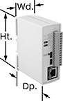
With a built-in web server, these relays can be remotely controlled over any IP network, including the Internet. They connect to your network either wirelessly or with an Ethernet cable (not included). No programming or software is required to operate these relays. Instead, use your web browser to input the relay’s IP address and the website guides you through simple menus and drop-down lists to set your parameters. Alternatively, you can use these relays with a PLC or without a computer at all if you use one relay as a controller for another relay.
Each circuit has a digital input that can be used to control the relay or a remote relay over the IP network. You could also use the digital input to monitor a separate device, such as a push-button or door alarm switch. These relays can be set to automatically restart network devices, such as computers, even when they fail to respond to relay signals. LED indicators let you know if there’s input and output voltage and if the network is connected and active. All meet at least one safety standard.
Mount these relays on 35 mm DIN rail (also known as DIN 3 rail) for fast installation. They also mount to flat surfaces.
Relays that control 2 circuits can also be programmed from a downloadable app or programs written in BASIC script, making them easy to customize. The website logs and stores data and device information.
Power over Ethernet (PoE) compatible relays can receive power from PoE cables (not included).
![]() For technical drawings and 3-D models, click on a part number.
For technical drawings and 3-D models, click on a part number.
Digital Inputs | Digital Outputs | ||||||||||||||||
|---|---|---|---|---|---|---|---|---|---|---|---|---|---|---|---|---|---|
| Number of Terminals | Voltage | No. of | Voltage | No. of | Control Current, A | Switching Current @ Voltage | Max. Switching Voltage | Ht. | Wd. | Dp. | Connection Type | Power Over Ethernet Standard | Communication Protocol | Operating System Compatibility | Features | Each | |
2 Circuits Controlled with 1 Off (Normally Open) or 1 On (Normally Closed)—SPDT | |||||||||||||||||
| 14 | 4V DC, 6V DC, 12V DC, 24V DC | 2 | 3V DC, 5V DC, 11V DC, 23V DC | 2 | 3 | 3 A @ 24 V DC | 24V DC | 3.9" | 1.4" | 3.1" | Ethernet | __ | Modbus TCP/IP, SMTP | Android 6.0 or Later, iOS 9 or Later, Windows XP or Later | LED Indicators, Data Logging Capabilities | 0000000 | 0000000 |
| 14 | 4V DC, 6V DC, 12V DC, 24V DC | 2 | 11V DC | 2 | 3 | 3 A @ 24 V DC | 24V DC | 3.9" | 1.4" | 3.1" | Ethernet | PoE, Type 1 | Modbus TCP/IP, SMTP | Android 6.0 or Later, iOS 9 or Later, Windows XP or Later | LED Indicators, Data Logging Capabilities | 0000000 | 000000 |
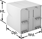
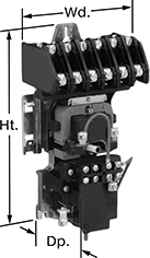
High-Current Lighting Relays
Switch lighting systems on and off—these relays can handle the high switching current on large overhead light systems. They control multiple circuits, so you can manage several lights across your facility with just one relay. For example, use them to switch overhead lights along with lighted signs in different parts of your warehouse. These relays come set for normally-open switching, but you can change them to normally-closed by turning the contacts around with a screwdriver.
Electrically held relays can handle switching on and off frequently. However, because they need constant input voltage to keep the relay switched, they make a humming noise when switched on.
Mechanically held relays are ideal for applications that don’t need to be switched very often, such as lights that stay on all day. Since they switch on and off with a quick burst of input voltage rather than needing constant power, they’re more energy efficient than electrically held relays.
| Number of Terminals | Input Voltage | Control Power | Switching Current @ Voltage (Light Technology) | Max. Switching Voltage | Mechanical Life Cycles | Ht. | Wd. | Dp. | Each | |
6 Circuits Controlled with 6 Off (Normally Open)—6PST-NO | ||||||||||
|---|---|---|---|---|---|---|---|---|---|---|
| 14 | 120V AC | 30VA | 30 A @ 120 V AC (Fluorescent) 20 A @ 120 V AC (Tungsten) | 132V AC | 4,000,000 | 5" | 4.3" | 3.1" | 0000000 | 0000000 |
| 14 | 277V AC | 30VA | 30 A @ 277 V AC (Fluorescent) 20 A @ 277 V AC (Tungsten) | 300V AC | 4,000,000 | 5" | 4.3" | 3.1" | 0000000 | 000000 |
| Number of Terminals | Input Voltage | Control Power | Switching Current @ Voltage (Light Technology) | Max. Switching Voltage | Mechanical Life Cycles | Ht. | Wd. | Dp. | Each | |
6 Circuits Controlled with 6 Off (Normally Open)—6PST-NO | ||||||||||
|---|---|---|---|---|---|---|---|---|---|---|
| 14 | 120V AC | 30VA | 30 A @ 120 V AC (Fluorescent) 20 A @ 120 V AC (Tungsten) | 132V AC | 1,000,000 | 8.8" | 4.3" | 3.3" | 0000000 | 0000000 |
Relay Sockets

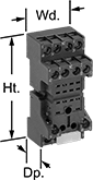
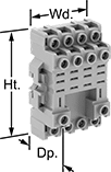
Mount to 35 mm DIN rail (also known as DIN 3 rail) or flat surfaces, then plug your relay into these sockets for fast installation.
Recessed terminals prevent contact with live connections.
Hold-down clips (sold separately) secure the socket in applications subject to vibration.
Relay Sockets | Hold-Down Clips | ||||||||||||
|---|---|---|---|---|---|---|---|---|---|---|---|---|---|
| No. of Terminals | For Quick-Disconnect Tab Wd. | For Switching Current @ Voltage | For Max. Switching Voltage | Ht. | Wd. | Dp. | Features | Each | Pkg. Qty. | Pkg. | |||
For Relays with Quick-Disconnect Terminals | |||||||||||||
With Screw Terminals | |||||||||||||
| E | 14 | 0.11" | 10 A @ 300 V AC | 300 V AC | 2.5" | 1.2" | 1" | __ | 0000000 | 000000 | 1 | 0000000 | 00000 |
| E | 14 | 0.2" | 12 A @ 240 V AC | 240 V AC | 3.1" | 1.8" | 1.3" | Recessed Terminals | 0000000 | 00000 | 2 | 0000000 | 000 |
| F | 14 | 0.11" | 10 A @ 300 V AC | 300 V AC | 2.6" | 1.2" | 1.1" | Recessed Terminals | 0000000 | 00000 | 1 | 0000000 | 000 |
| G | 14 | 0.197" | 10 A @ 300 V AC | 300 V AC | 2.7" | 2" | 1.2" | Recessed Terminals | 0000000 | 00000 | 1 | 0000000 | 000 |
| J | 14 | 0.11" | 10 A @ 300 V AC | 300 V AC | 3.1" | 1.2" | 1.6" | Recessed Terminals | 0000000 | 00000 | __ | 000000 | 00 |
| J | 14 | 0.187" | 15 A @ 120 V AC | 300 V AC | 3.1" | 2" | 1.2" | Recessed Terminals | 0000000 | 00000 | __ | 000000 | 00 |
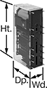
Solid State DIN-Rail Mount Multifunction Timer Relays
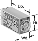
For fast installation, mount these relays to 35 mm DIN rail (also known as DIN 3 rail). They also mount to flat surfaces. With no moving parts, these solid state relays last longer and require less maintenance, are quieter, and switch faster than mechanical relays. They provide a variety of timing functions in one relay.
Use relays with DIP switches for more precise control than knobs. They make it easier to set multiple relays to the same timing range.
Relays that control 4 circuits require a relay socket (sold separately) to attach to DIN rail.
Timer Relays | ||||||||||||||
|---|---|---|---|---|---|---|---|---|---|---|---|---|---|---|
Timing Range | Relay Sockets | |||||||||||||
| No. of Terminals | Input Voltage | Control Current, mA | Timer Relay Function | No. of | O'all | Switching Current @ 240V AC | Max. Switching Voltage | Ht. | Wd. | Dp. | Each | Each | ||
Relays with Knob | ||||||||||||||
4 Circuit Control with 4 Off (Normally Open) or 4 On (Normally Closed)—4PDT | ||||||||||||||
| 14 | 120V AC | 15 | Delayed Start (Delay-on-Make) Interval Repeat Cycle | 4 | 0.1 sec.-10 min. | 3A | 250V AC | 1.1" | 0.9" | 2.1" | 000000 | 0000000 | 0000000 | 000000 |
| 14 | 240V AC | 9 | Delayed Start (Delay-on-Make) Interval Repeat Cycle | 4 | 0.1 sec.-10 min. | 3A | 250V AC | 1.1" | 0.9" | 2.1" | 000000 | 000000 | 0000000 | 00000 |
| 14 | 24V DC | 45 | Delayed Start (Delay-on-Make) Interval Repeat Cycle | 4 | 0.1 sec.-10 min. | 3A | 250V AC | 1.1" | 0.9" | 2.1" | 000000 | 000000 | 0000000 | 00000 |