
How to Choose a Gear
Found in a wide variety of machines—from conveyors, blowers, and fuel pumps to elevators, drawing machines, and rock crushers—gears connect two rotary shafts to change a system's speed, torque, and angle. When a gear is used with a gear rack, it converts rotary motion into linear motion.
When selecting gears and gear racks, you'll need to know the gear type, pressure angle, and pitch (or for metric gears, module). As long as these three specifications are the same, your gears will fit together correctly.
Types of Gears
Gear type is determined by the shape of the gear's teeth and the direction of motion the gears transmit.
-
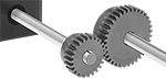
Spur

The simplest type of gear, spur gears and racks, have straight-cut, parallel teeth that work well for moderate-load, moderate-speed applications or for high-speed applications where noise and vibration are not a concern.
Combine two differently sized gears to change speed and torque in your assembly, or combine a gear and rack to convert rotary motion into linear motion.
-
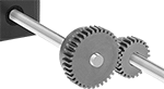
Helical
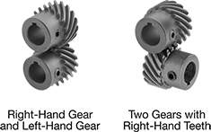
For smooth, quiet operation at high speeds under heavy loads, helical gears have curved teeth that engage gradually and stay in contact longer than straight teeth. Because the curved teeth create thrust loads (loads that are parallel to the shaft), helical gear systems often require thrust bearings to prevent wear from misalignment.
Helical gears can be configured to transmit motion in a straight line or at a 90° angle. To transmit motion in a straight line, use one left-hand and one right-hand gear. To transmit motion at a 90° angle, pair two gears with the same tooth direction.
-
Miter

Miter gears have straight teeth and a conical profile for transmitting motion at a right angle without changing shaft speed or torque. They're more efficient than spiral miter gears, which means they require less power to do the same work; however, they are noisier when run at high speeds and under heavy loads. Configure in pairs.
-
Spiral Miter

Spiral miter gears have curved teeth that gradually engage and stay in contact longer than straight teeth so they handle heavier loads at higher speeds. They run smoother and quieter than standard miter gears but are not as efficient, which means they require more power to do the same work. Furnished as a pair, they transmit motion at a right angle while maintaining shaft speed and torque.
-
Bevel
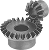
Similar to miter gears, bevel gears have straight teeth and a conical profile for transmitting motion at a right angle. Unlike miter gears, one of the gears (sometimes called a pinion) is smaller than the other. Combine a pinion and gear for right-angle speed reduction at ratios ranging from 2:1 to 4:1.
-
Worm
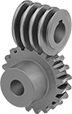
Worm gears use screw threads to reduce shaft speed by ratios of 18:1 and greater while transmitting motion at a right angle. Unlike bevel gears, worm gears operate in one direction only; they transmit motion from worm to gear and cannot be reversed.
-
Ratchet
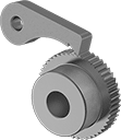
Used to prevent unwanted motion in jacks, tie downs, clutches, and winches, ratchet gears have sloped teeth to engage with a pawl to allow motion in one direction and prevent it in the other.
Pressure Angle
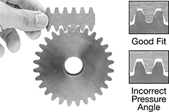
Pressure angle determines how gear teeth fit together as they mesh. In order to work together, gears must have the same pressure angle. Gears with a 20° pressure angle (the current industry standard) have thicker, stronger teeth than gears with a 14 1/2° pressure angle. Gears with a 14 1/2° pressure angle (the former industry standard) are often found on older machinery.
To measure the pressure angle and pitch or module of a gear, use a Gear Tooth Pitch Identifier.
Pitch and Module
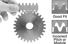
Pitch and module represent the size and spacing of a gear's teeth. Pitch is used for inch gears; module for metric. Gears must have the same pitch or module in order to work together.
To measure the pressure angle and pitch or module of a gear, use a Gear Tooth Pitch Identifier.
If you don't have a gear tooth pitch identifier, you can estimate a spur gear's pitch or module.
Inch
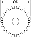

To estimate the pitch of an inch gear, first count the number of teeth and add 2 to the total. Next, divide the result by the OD of the gear in inches. Round to the nearest whole number. For example, a gear with 32 teeth and an OD of 2.13" has a pitch of 16.
Metric
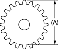

To estimate the module of a metric gear, first measure the distance in mm from the tip of the teeth on one end of the gear to the base of the teeth on the other end (A). Then, divide the result by the number of the teeth. For example, a gear with an (A) measurement of 40 mm and 20 teeth has a module of 2.
Changing Shaft Speed Using Spur and Helical Gears
To change the shaft speed of an electric motor or other power source, mesh two gears that have different numbers of teeth. Changing shaft speed also changes torque, as speed decreases, torque increases.
Decrease speed by transmitting motion from a gear with fewer teeth to a gear with more teeth. Torque increases.
Increase speed by transmitting motion from a gear with more teeth to a gear with fewer teeth. Torque decreases.
To determine the approximate amount of speed change a pair of gears will provide, compare the number of teeth. For example, combining a 32-tooth gear and a 16-tooth gear will change speed at a ratio of 32:16 (or 2:1). Combining a 48-tooth gear and a 12-tooth gear will change speed at a ratio of 4:1. This ratio is also known as gear ratio and speed ratio.
Calculating Mounting Distance for Spur and Helical Gear Components
-
For Two Gears

To calculate the mounting distance for two gears, add the two pitch diameters and divide the result by two.
-
For a Gear and Internal Gear

To calculate the mounting distance for a gear paired with an internal gear, subtract the smaller pitch diameter from the large pitch diameter, then divide the result by two.
-
For a Gear and Rack

To calculate the mounting distance for a gear and rack, divide the pitch diameter of the gear by two and add the result to the pitch height of the gear rack.
Choose from our selection of gears. In stock and ready to ship.